MOONEY INTERNATIONAL CORPORATION
M20V SERVICE AND MAINTENANCE MANUAL
Date
MAR 2017
Rev Date
Page
9
LANDING LIGHTS, NAVIGATION LIGHTS AND TAILLIGHT
Lamp fails to light.
Lamp burned out. Replace lamp.
Loose connection or
defective wire.
Tighten connections and check wire
circuit continuity. Replace or repair
wire if necessary.
Circuit breaker/switch
defective.
Check continuity through switch.
Replace if necessary.
Defective ballast (xenon bulbs) Replace ballast.
Lamp fails to light. Circuit breaker/switch
tripped.
Check for short circuit. Reset cir-
cuit breaker.
Individual LED segment fails to
illuminate.
Defective assembly. Replace assembly.
33-41-00 - HIGH INTENSITY STROBE LIGHTS-
MAINTENANCE
The strobe light power supply requires a 28 VDC input
across red and black wires. Red is positive and black is
negative or common. Voltage for strobe light is supplied
through Pin 1 and 3 of power supply connector with Pin
2 as trigger pulse. The strobe light assembly is a potted
assembly and cannot be repaired.
TROUBLESHOOTING AIDS
When no lights are flashing:
1. Check circuit breaker/switch.
2. To determine if power supply(ies) or flashtube(s)
problem, first check input voltage to power supply(ies).
Each power supply’s red and black line should have 28
VDC. If no voltage is present, check for shorted power
leads or tripped circuit breaker.
When one light is not flashing:
1. To determine if power supply or flashtube problem:
first check input voltage to power supply. The red and
black line should have 28 VDC. If no voltage is present
then check for shorted power leads, blown inline fuses
or circuit breaker. If input voltage is present, disconnect
connector to flashtube. 400- 500VDC should be pres-
ent across Pin 1 and 3 of power supply. If not, power
supply has no output and is defective. Turn Master
Switch - OFF, replace power supply.
2. If voltage is present across Pin 1 and 3 of power
supply, connect a known good flashtube to power sup-
ply. If good flashtube fails to operate, power supply is
defective. If good flashtube operates, the old flashtube
is defective. Replace flashtube.
33-41-01 - POWER SUPPLY(IES) UNIT- REMOVAL
OR REPLACEMENT
1. Tail Strobe light power supply.
A. Gain access to this unit through inspection cov-
er on aft, left hand side of tailcone. The power supply is
physically mounted to this inspection cover.
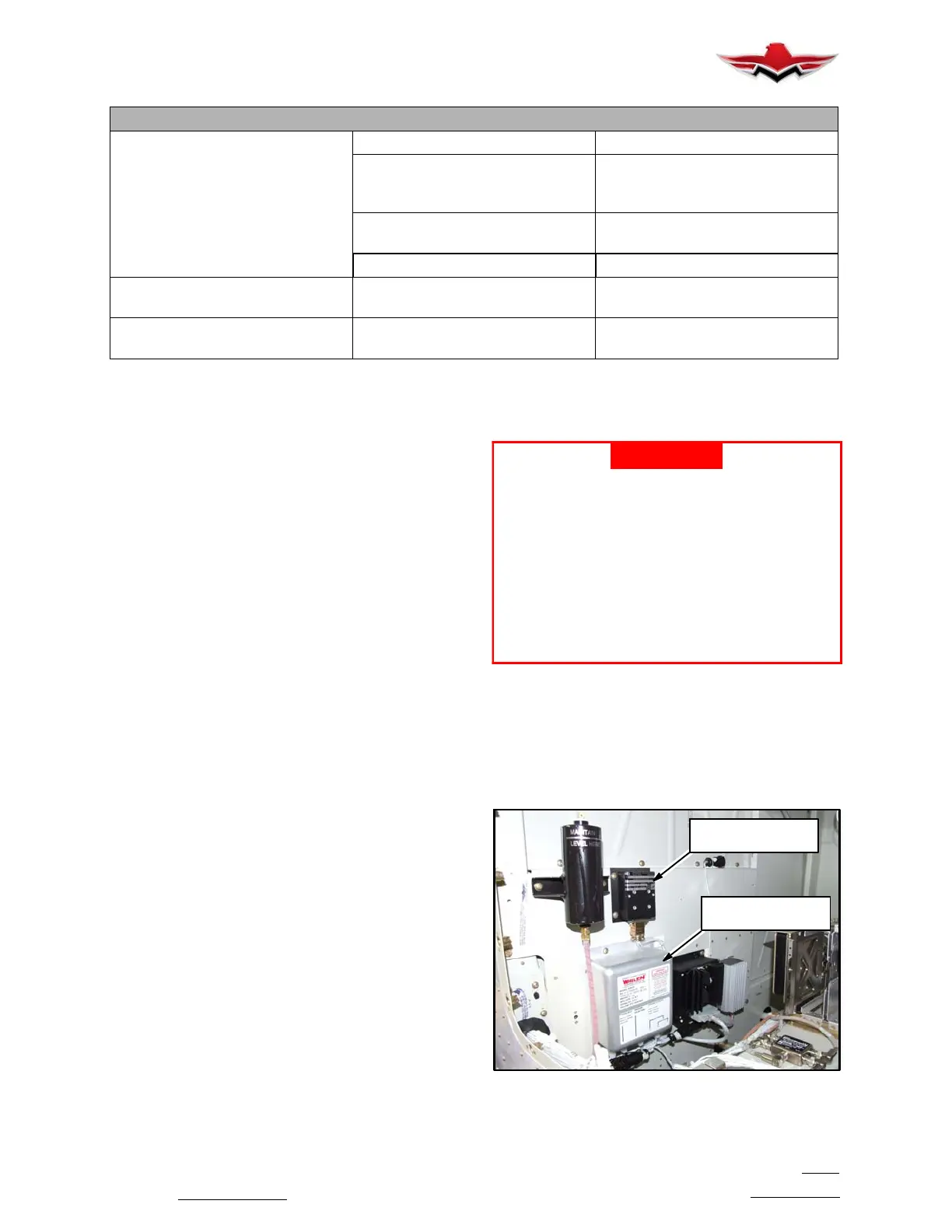
2. Wing Tip light power supply and Baggage Light
control box.
A. Gain access through the L/H battery panel, and
the units are mounted on the baggage wall (Figure
33- 4).
-WARNING-
High voltage is involved in circuit between
power supply and strobe light assemblies.
Although a bleed- off resistor is incorporated
in power supply circuit, turn control switch,
for strobe lights OFF. Allow at least 20 min-
utes to elapse prior to disconnecting cables
at power supply or strobe light assemblies or
before handling either of these units in any
way. Failure to observe these precautions
may result in physical injury from electrical
shock.
B. Disconnect wiring connections between switch
and power supply(ies).
C. Disconnect wire harness between power sup-
ply(ies) and strobe light.
D. Remove screws securing power supply(ies) to
inspection panel and remove unit.
BAGGAGE LIGHT
CONTROL BOX
WING TIP
POWER SUPPLY
BAGGAGE WALL - POWER SUPPLIES
FIGURE 33- 4
33-40-01
 Loading...


