MOONEY INTERNATIONAL CORPORATION
M20V SERVICE AND MAINTENANCE MANUAL
Date
MAR 2017
Rev Date
Page
10
33-41-02 - POWER SUPPLY(IES) UNIT I NSTALLA-
TION
The installation of power supply(ies) is reverse se-
quence of removal procedures.
-CAUTION-
STROBE LIGHT WIRING - An incorrect hook-
up of wires, at either the power input or be-
tween strobe light assemblies and power
supply unit will cause a reversal of polarity
that results in serious component damage
and failure. Care must be taken to ensure that
the red wire is connected to positive power
and the black wire to ground.
33-41-03 - STROBE/NAVIGATION LIGHT RE-
PLACEMENT
1. WING TIP STROBE/NAVIGATION LIGHT:
The following information is to assist you in installing a
Whelen light system. The installation procedure de-
scribed in the following text will be confined to a single
light installation, but is identical for multiple light install-
ations.
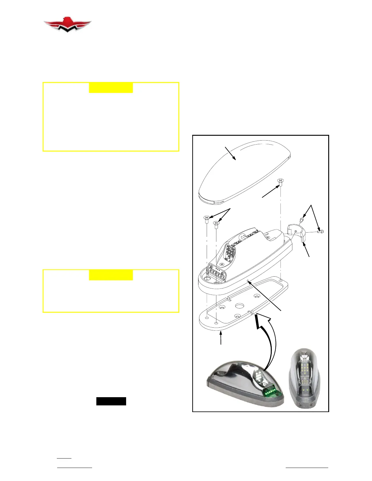
A. Carefully remove the #2 cap head screws and lens
retainer. Remove the lens from the light assembly by
lifting the rear of the lens approximately 1/2”. Now slide
the lens rearward approximately 1/2” and lift upwards
to remove.
-CAUTION-
Do not touch the LED lens surface with either
fingers or sharp objects. This could soil and/
or damage the lens and affect the optical per-
formance of the LEDs.
Remove the 3 black Phillips head screws securing the
baseplate to the light assembly. Remove baseplate.
B. Using the appropriate hardware install the base-
plate to the aircraft.
C. Connect (or Disconnect if removing) the light
power lead harness.
D. Re- install the light assembly on to the baseplate
and insure that all leads are clear of any obstructions
and secured as required.
-NOTE-
Proper orientation is achieved with the drain hole
down.
E. Install lens in the reverse order as removal, return
the lens retainer to its installed location, re- insert #2
cap head screw and tighten firmly. Confirm proper gas-
ket fit.
F. When necessary, waterproof the light base to air-
craft. Apply single- part Silicone (RTV) or equivalent
around any open area where water could get in. Do not
cover the drain hole.
G. Check all avionics systems for interference from
this installation.
H. A flight check should be performed by a properly
certified pilot.
LENS
BASEPLATE
DRAIN HOLE
2-56 X 3/16
CAPSCREWS
4-40 X 5/16
SCREWS
MS24693-3B
LENS
RETAINER
OR6002
ASSEMBLY
WING TIP LIGHTS
FIGURE 33- 5
33-41-02
 Loading...


