MOONEY INTERNATIONAL CORPORATION
M20V SERVICE AND MAINTENANCE MANUAL
Date
MAR 2017
Rev Date
Page
11
5
6
3
2
4
1
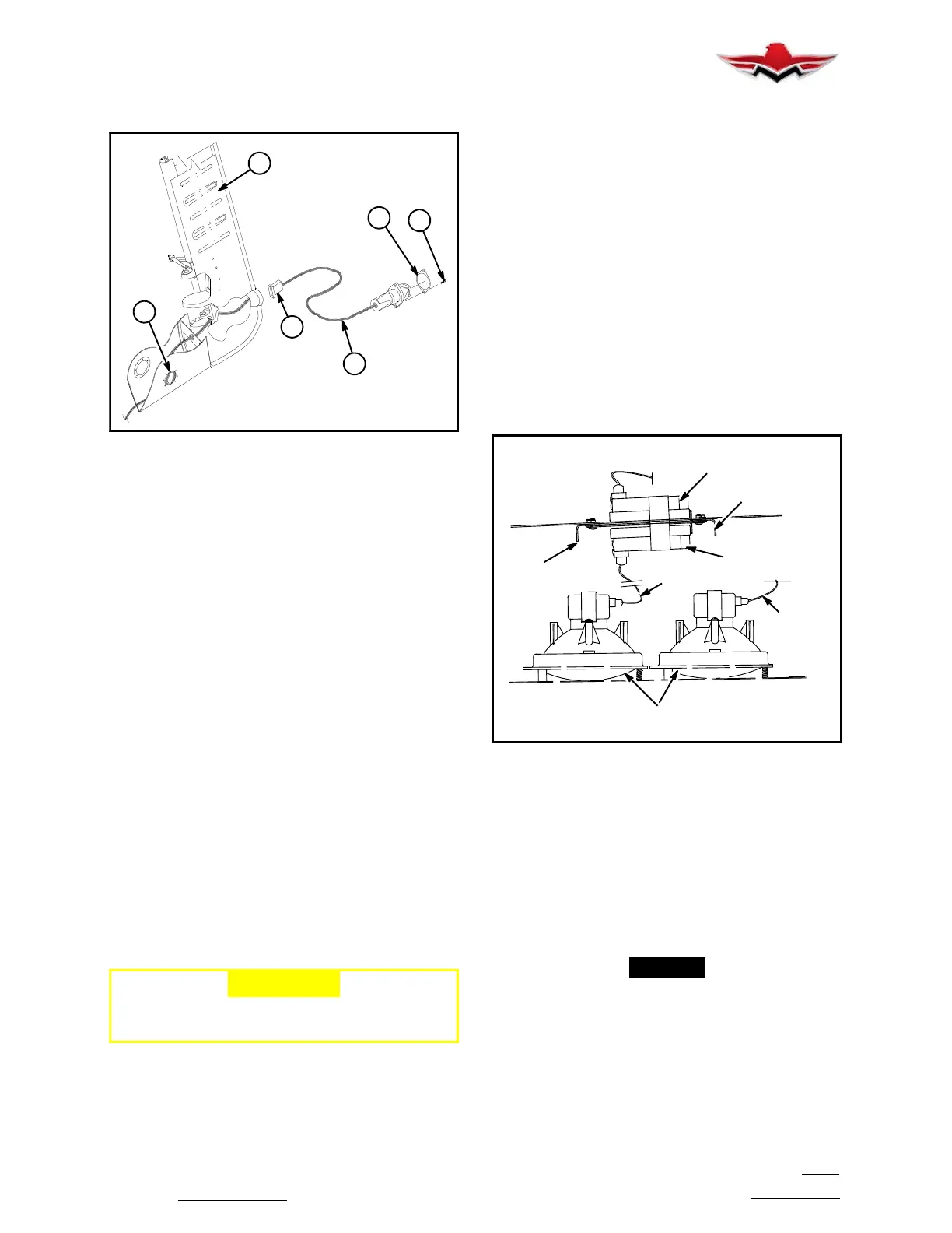
TAIL STROBE LIGHT ASSEMBLY
FIGURE 33- 6
2. TAIL STROBE REMOVAL.
A. To gain access to wire harness and connections
from power supply, rotate round access cover (1) on
lower left side of empennage stinger (Figure 33- 6)
around one screw.
B. Cut Ty- raps at harness coil (1) to allow slack for
strobe light assembly and harness to be extended be-
yond rudder.
C. Remove two screws (3) that secure retainer and
strobe light assembly to rudder (4) and pull light assem-
bly out so it clears mounting hole.
D. There is sufficient wire available to pull strobe
light assembly out from rudder light mounting hole. See
(Figure 33- 4). Disconnect light assembly pigtail (5)
from connector at (6) and replace assembly if needed.
E. Connect plug from strobe light assembly to har-
ness socket at (6).
F. Secure light assembly with retainer and screws.
G. Check for proper operation.
H. Coil harness at (1) to take up slack.
I. Secure access cover on empennage.
33-43-00 - LANDING/TAXI LIGHTS
33-43-01 - LANDING/TAXI LIGHT ADJUSTMENT
PROCEDURES
-CAUTION-
Do not attempt this procedure with aircraft
engine operating.
1. Position aircraft to face a vertical wall with front of
nose wheel 7 ft. 6 in. from wall. Position L/H & R/H main
landing gear at exact distance from vertical wall, i.e.
parallel to wall.
2. Place four target crosses (+) on vertical wall at the
following positions:
A. Measure 36.5 inches UP on vertical wall from
same ground plane aircraft is resting on.
B. At 9.85 feet, left and right, of nose wheel center
line.
C. At 12.375 inches further outboard on both left &
right side of Step B. target position.
3. Remove access cover behind each landing/taxi
light location on wing lower surface.
4. Turn taxi lights ON, exit aircraft, turn adjusting
screws until light beams are centered on outboard tar-
get crosses (+), left and right.
5. Repeat Step 4 for landing lights, except, center
light beams on inboard target crosses, left & right.
6. Turn lights OFF, reinstall access covers.
TAXI LIGHT
BRACKET
BALLAST ASSY.
LANDING LIGHT
BALLAST ASSY.
XENON
LIGHT
CABLE
ASSY.
ASSY.
BRACKET
ASSY.
CABLE
ASSY.
XENON LANDING/TAXI LIGHT ASSEMBLY
(OPTIONAL)
FIGURE 33- 7
33-43-02 - LANDING/TAXI LIGHT BULB RE-
PLACEMENT
1.
Remove access
cover (see 33- 43- 01, 3 above).
2. Carefully remove electrical plug connection from
bulb.
3. Loosen socket head mounting screws to remove
retainer.
-NOTE-
Do not loosen or turn screws that adjust light
bulb positioning focus in mounting brackets.
4. Rotate retainer to large slotted holes and pull re-
tainer from bulb.
5. Pull retainer from access hole.
6. Pull bulb from plate assembly and through access
hole.
33-41-03
 Loading...


