MOONEY INTERNATIONAL CORPORATION
M20V SERVICE AND MAINTENANCE MANUAL
Date
MAR 2017
Rev Date
Page
5
34-00-00 - GENERAL
M20V aircraft are equipped with a GARMIN G1000 In-
tegrated Avionics System utilizing two Garmin
10XX
Multi Function Display
Units (CDUs) installed in the
M20 instrument panel. One is configured as a Primary
Flight Display (PFD) and the other as a Multi- Function-
al Display (MFD). The displays are located side- by-
side, with the GMA 1347 Audio Panel located in the
middle.
The PFD displays graphical flight instrumentation in
place of traditional gyro instruments. Attitude, heading,
airspeed, altitude, and vertical speed are all shown on
one display. The MFD shows a full- color moving map
with navigation information. Both displays offer control
over COM and NAV frequency selectors, as well as
heading, course/baro and altitude reference functions.
On the left of the MFD display, an Engine Indication
System (EIS) cluster shows graphical depictions of en-
gine and airframe instrumentation.
Both displays are installed in the instrument panel us-
ing built- in ¼- turn fasteners. Each display uses a
single Garmin 62- pin connector. Electrical power to
both the PFD and MFD is supplied from the ‘Essential’
buss.
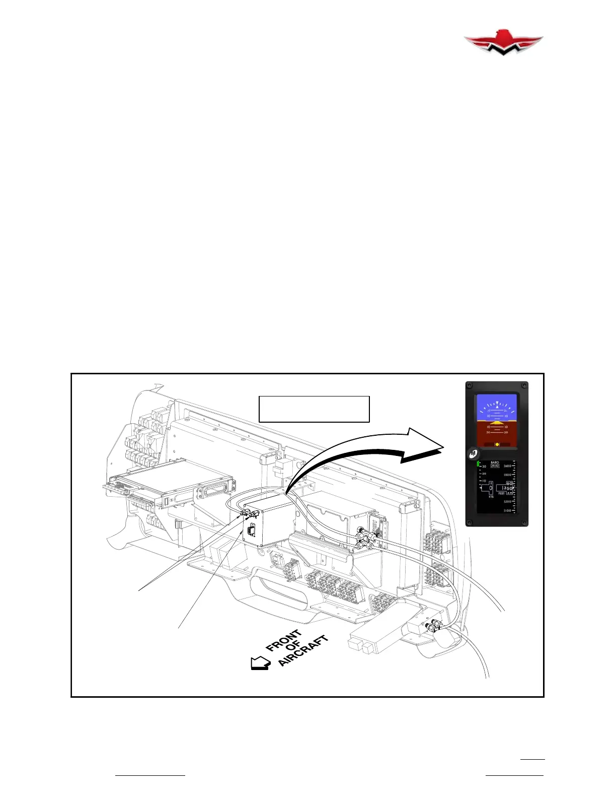
The Mid- Continent model MD302 series Standby Atti-
tude Module (known as the SAM) is a self- contained
situational awareness instrument that provides aircraft
attitude, altitude, airspeed and slip indication, in an ad-
vanced 2- inch format. The self- contained, re-
chargeable, emergency battery offers pilots an in-
creased level of security. In Pre- flight mode, the
introduction screen will be displayed for approximately
five seconds and will transition to Flight Mode when
complete. In Flight Mode, the unit operates normally by
displaying all four major functions: Attitude, Altitude,
Airspeed and Slip Information see Figure 34-1.
A “Traditional” magnetic compass is mounted on the
windshield center post.
Service, maintenance and troubleshooting instructions
specific to the Garmin G1000 Integrated System are
provided in the Garmin G1000 Line Maintenance and
Configuration Manual
and G1000 System Mainten-
ance Manual
(#190 - 00907- 00 Rev E).
The glareshield must be removed and plumbing dis-
connected on SAM Module before it can be removed.
Remove glareshield attaching screws, center post cov-
er screws. Carefully lift center post cover and glare-
shield from panel. Disconnect glareshield and com-
pass lights.
Reinstall glareshield in reverse sequence.
FRONT OF
REF: STANDBY ATTITUDE
MODULE (SAM)
REF: PNEUMATIC
CONNECTORS
PITOT
STATIC
LOOKING AT REAR
OF INSTRUMENT PANEL
BACK OF
MFD
BACK OF
PFD
ATTITUDE
MODULE
STANDBY
(SAM)
REAR VIEW OF INSTRUMENT PANEL
FIGURE 34-1
34- 00-00
 Loading...


