MOONEY INTERNATIONAL CORPORATION
M20V SERVICE AND MAINTENANCE MANUAL
Date
MAR 2017
Rev Date
Page
11
Liquid leakage.
Loose bezel screws. Tighten screws.
Broken cover glass. Replace instrument.
Defective sealing gaskets. Replace instrument.
Discolored luminous markings or
discolored damping liquid.
Age Replace instrument.
Defective light. Burnt out lamp or broken circuit. Check lamp or wiring continuity.
34-23-00 - ATTITUDE INDICATOR
STANDBY ATTITUDE MODULE (SAM)
ATTITUDE
The attitude indicator portion of the SAM display will al-
ways appear on the left display when the unit is oriented
horizontally and on the top display when oriented ver-
tically. An example of the attitude display is shown in
Figure 34-2 and Figure 34-4.
The background of the display consists of the repres-
entative white horizon line separating the “sky” (blue)
and “ground” (brown).
The roll scale is depicted as an arc of graduations rep-
resenting bank angles of 0 (triangle), 10, 20, 30, 45
(small triangle), and 60. The roll scale can be con-
figured during installation to be fixed to the sky/horizon
or fixed to the top of the display. See Section 3 of the
Mid- Continent Instruments Manual Number 9017782
Dated Oct 31, 2013 Rev B or later revision for how to
configure this option. The unit is operable and usable
in a continuous and unlimited roll range of 360+.
The roll pointer is the triangle just below the roll scale
and represents the aircraft in relation to its bank angle.
It is configured, by definition, to operate conversely to
the roll scale behavior. That is, a rotating roll scale pro-
duces a fixed roll pointer and a fixed roll scale produces
a rotating roll pointer.
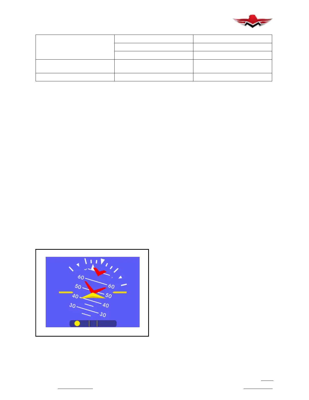
ATTITUDE OPERATION (SAM)
FIGURE 34-5
The pitch scale is depicted as a series of graduations
representing pitch angles of every 5,withevery10
graduation extended and numbered. The unit is oper-
able and usable in a continuous and unlimited pitch
range of 360+. A series of chevrons (^) will appear
overlaid on the pitch scale as seen in Figure 34-5.This
is to indicate to the pilot the direction of the horizon for
quick reference when in unusual pitch attitude.
The symbolic airplane will always remain in the center
of the display, with the background elements moving
behind it to represent the aircraft’s relative position.
The symbol that represents the airplane can be selec-
ted during Flight Mode using the Options Menu.
ATTITUDE (G1000)
The G1000 attitude information displays over a virtual
blue sky and brown ground with a white horizon line.
The aircraft wing tips are represented by two yellow
bars on the horizon line. The yellow inverted “V” repre-
sents the aircraft. The Attitude indicator displays the
following information:
Pitch indication
Roll indication
Slip/Skid indication
Pitch Indication:
Major pitch marks and numeric labels at 10,20,30,
40,50,60,70 and 80 are shown above and below
the horizon line. Minor pitch marks at 5,15 and 25
above the horizon line and 5,15,25,35 and 45 be-
low the horizon line are shown. The horizon line is part
of the pitch scale. Red extreme pitch warning chevrons
pointing toward the horizon are displayed starting at
50 above and 30 below the horizon line.
Refer to Garmin G1000 Maintenance manual for trou-
bleshooting and service information.
34-90-00 - MISCELLANEOUS INSTRUMENTS
34-90-01 - CLOCK
A real- time clock is integral to the Garmin G1000
Avionics System.
34-90-02 - OUTSIDE AIR TEMPERATURE
The Garmin GTP 59 OAT Probe provides the GDC 74A
with air temperature data. The OAT probe is mounted
to the bottom side of the right wing.
Refer to G1000 Line Maintenance and Configuration
Manual for service and troubleshooting information.
34-23-00
 Loading...


