MOONEY INTERNATIONAL CORPORATION
M20V SERVICE AND MAINTENANCE MANUAL
Date
MAR 2017
Rev Date
Page
10
30 is found at any cardinal heading, proceed to
demagnetize cockpit as outlined in Step 3. If error is
less than 30 at any cardinal heading, proceed to
swing compass (Step 4).
3. Demagnetize Cockpit:
-CAUTION-
Improper use of a growler can induce more
magnetism in cabin structure, making exten-
sive demagnetizing necessary.
A. Remove compass from cockpit.
B. Position aircraft at a heading of either 90 or
270.
C. Make sure growler is turned OFF. Place growler
in cockpit, position seats aft and support power cord so
that it does not touch or pass within six inches of any
structural member.
D. While sitting, straddling pilot and co- pilot seats,
hold growler inside cockpit center in a low position.
Turn growler ON and slowly move it forward, close to
instrument panel centerline, up toward and along wind-
shield center post and along overhead structure over
and to behind your head. Move growler down in a circu-
lar motion from behind shoulders to waist or mid- chest
height before turning it OFF.
-NOTE-
Windshield center post is fabricated of non- mag-
netic stainless steel. This post requires no de-
magnetizing.
E. Hold compass in place to see if headings now
match aircraft heading. If too much heading error (more
than 15) still exists, remove compass from aircraft.
F. Turn growler ON and move it along center side
and overhead cross structure from one side of cockpit
to the other. Turn OFF growler.
G. Again, hold compass in place and compare
headings. If heading error has not reduced sufficiently
(to less than 15), then:
1) Repeat steps D, E, F and G.
H. When heading error is reduced to less than
15, install compass and proceed to Step 4 – Compass
Swinging.
4. Compass Swinging:
A. Run engine at 1200 to 1500 RPM and proceed
to swing compass with radio “ON” after reinstalling and
centering compensator magnets (if removed).
B. Position aircraft on compass rose and adjust
N- S compass compensating screw (left screw) for a 0
indication at north heading (Use non- ferrous tools).
C. Turn aircraft to east heading and adjust com-
pass E- W compensator screw (right screw) for a 90
indication.
D. With aircraft on south heading adjust N- S com-
pensator to reduce indicated error by 50 percent (ex-
ample: If compass reads 184, adjust compensators so
it reads 182).
E. With aircraft on west heading adjust E- W com-
pensator to reduce indicated error by 50 percent.
F. Return aircraft to north heading, reset directional
gyro and, using DG, check and record compass error at
every 30 heading through 360.
G. Adjust compensator making sure compass
reads within 10 at any heading and proceed to step
5. If compass does not read within 10 at any heading,
proceed to de- magnetize cockpit as outlined in Step 3.
5. Fill out compass correction card giving “Radio ON”
corrections through 360. Install card on or in close
proximity to compass in full view of pilot.
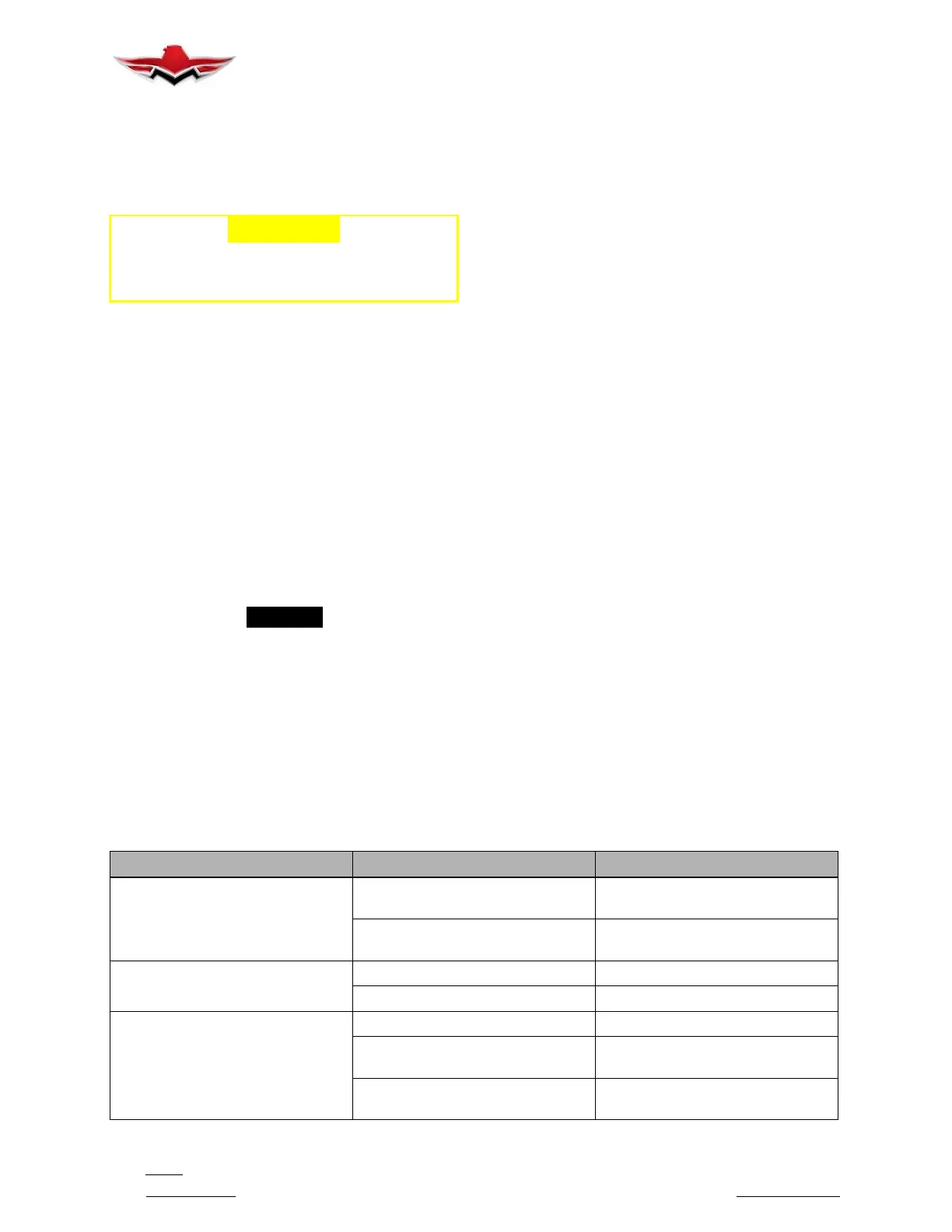
34-22-02 - COMPASS TROUBLESHOOTING (TRADITIONAL COMPASS)
TROUBLE PROBABLE CAUSE REMEDY
Excessive card error.
Compass not properly compen-
sated.
Compensate instrument.
External magnetic interference. Locate magnetic interference and
eliminate, if possible.
Excessive card oscillation.
Improper instrument mounting. Align instrument.
Insufficient liquid. Replace instrument.
Sluggish card.
Weak card magnets. Replace instrument.
Excessive pivot friction or broken
jewel.
Replace instrument.
Instrument too heavily compen-
sated.
Correct excess compensation.
34-22-02
 Loading...


