MOONEY INTERNATIONAL CORPORATION
M20V SERVICE AND MAINTENANCE MANUAL
Date
MAR 2017
Rev Date
Page
9
34-20-00 - G1000 HORIZONTAL SITUATION
INDICATOR (HSI)
The G1000 Horizontal Situation Indicator (HSI) dis-
plays a rotating compass card with letters at the cardi-
nal points and numeric labels every 30. Major tick
marks are at 10 intervals and minor tick marks for ev-
ery 5. The HSI is displayed in a heading up orientation.
The HSI compass can be displayed as a 360 rose or
140 arc. The HSI displays the following information:
Heading indication
Turn Rate indicator
Course Deviation Indicator
Bearing pointers
Bearing information windows
Navigation source
Refer to G1000 Line Maintenance and Configuration
Manual for Horizontal Situation Indicator (HIS) service
and troubleshooting information.
34-21-00 - SLIP/SKID INDICATOR
STANDBY ATTITUDE MODULE (SAM)
SLIP DISPLAY
Slip Indicator portion of the SAM unit will always ap-
pear at the bottom of the Attitude Display, see
Figure
34-2
. The Slip Indicator is represented by a shaded
translucent background with two white lines around
center and a white ball. When the ball is maintained
between the vertical lines during banking man-
euvers, the turn is considered “coordinated” without
slip see
Figure 34-4.
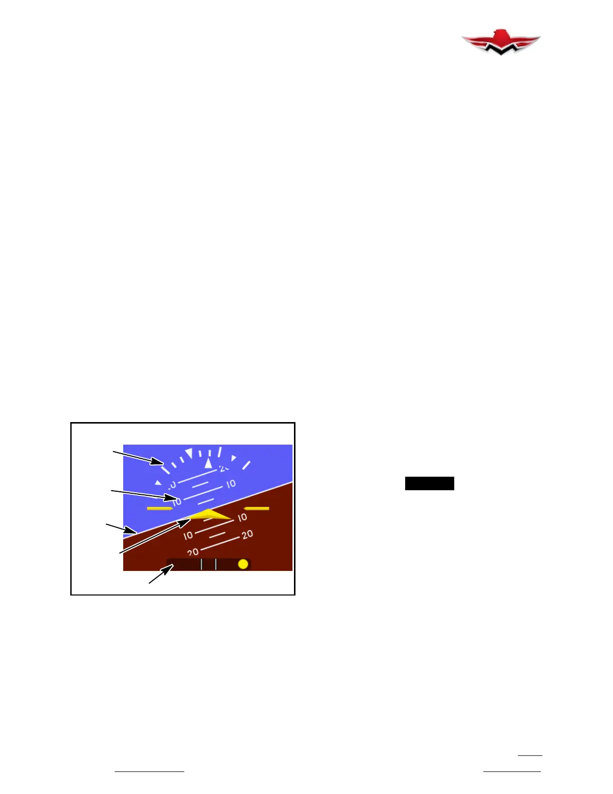
ROLL/BANK
SCALE
PITCH
SCALE
SLIP INDICATOR
SYMBOLIC
AIRPLANE
HORIZON
LINE
ATTITUDE/SLIP OPERATION (SAM)
FIGURE 34-4
The slip indicator is represented by a shaded translu-
cent background with two white lines around center
and a yellow ball. The ends of the indicator represent
7_ of bank with no centripetal acceleration. No further
indication is provided for angles greater than 7_. When
the ball is maintained between the vertical lines during
banking maneuvers, the turn is considered “coordin-
ated” without slip. Electronic damping of the ball move-
ment is provided to prevent overly sensitive response
and comply with regulatory requirements.
The slip indicator background becomes semi- trans-
parent if the roll scale or roll pointer pass behind the in-
dicator so that all elements are still visible.
SLIP/SKID DISPLAY (G1000)
The G1000 Slip/Skid indicator (a component of the Atti-
tude Indicator screen display) resides beneath the roll
pointer. The indicator moves with the roll pointer and
moves laterally away from the pointer to indicate lateral
acceleration. A slip/skid is indicated by the location of
the Slip/Skid indicator relative to the roll pointer. One
Slip/Skid indicator displacement is equal to one ball
displacement when compared to a traditional Slip/Skid
indicator.
Refer to G1000 Line Maintenance and Configuration
Manual for service and troubleshooting information.
34-22-00 - MAGNETIC COMPASS (TRADITIONAL)
The traditional magnetic compass dial, graduated in 5º
increments, is encased in a liquid filled glass and metal
case. The unit mounts on top of glareshield or on wind-
shield center post. The compass should be swung and
compensated at each annual inspection and whenever
new electrical equipment is installed.
To compensate for N- S deviation, adjust left screw; to
compensate for E- W deviation, adjust right screw.
Degaussing of tubular structure may be required if
compass cannot be compensated within limits. Care-
fully go over entire steel structure with degausser, from
center to outboard of structure (Left & Right), to remove
residual magnetism. It is recommended that an Arma-
ture Growler be used to degauss s
teel structure (Ref.
33- 22- 01). An Associated Growler/Armature Tes
ter
No. AOE- 6054, or similar devic
e, may be used.
-NOTE-
Check for outside magnetic influences if exces-
sive compensation is required.
A Horizontal Situation Indicator (HSI) is integral to the
Garmin G1000 system. This display indicates magnet-
ic heading, among other data. The traditional magnetic
compass, mounted on the windshield center post,
should be referenced as a backup instrument.
Refer to G1000 Line Maintenance and Configuration
Manual for adjustments and troubleshooting informa-
tion for the Horizontal Situation Indicator.
34-22-01 - DEMAGNETIZING AND COMPASS
SWINGING PROCEDURES (TRADITIONAL COM-
PASS)
Check aircraft for magnetized structure as follows:
1. Center or remove compensating magnets from
compass.
2. Position aircraft on compass rose, run engine at
1200 to 1500 RPM, and check the four cardinal head-
ings starting at north heading. If an error greater than
34-21-00
 Loading...


