MOONEY INTERNATIONAL CORPORATION
M20V SERVICE AND MAINTENANCE MANUAL
Date
MAR 2017
Rev Date
Page
5
35-00-00 - GENERAL
-WARNING-
Proper safety measures must be employed
while oxygen system maintenance is being
performed or a serious fire hazard will be
created. Avoid making sparks and keep all
burningcigarettesorfireawayfromvicinityof
oxygen. Make sure that your hands, tools, and
clothing are clean, particularly with respect to
oil or grease, for these will IGNITE upon con-
tact with pure oxygen under pressure.
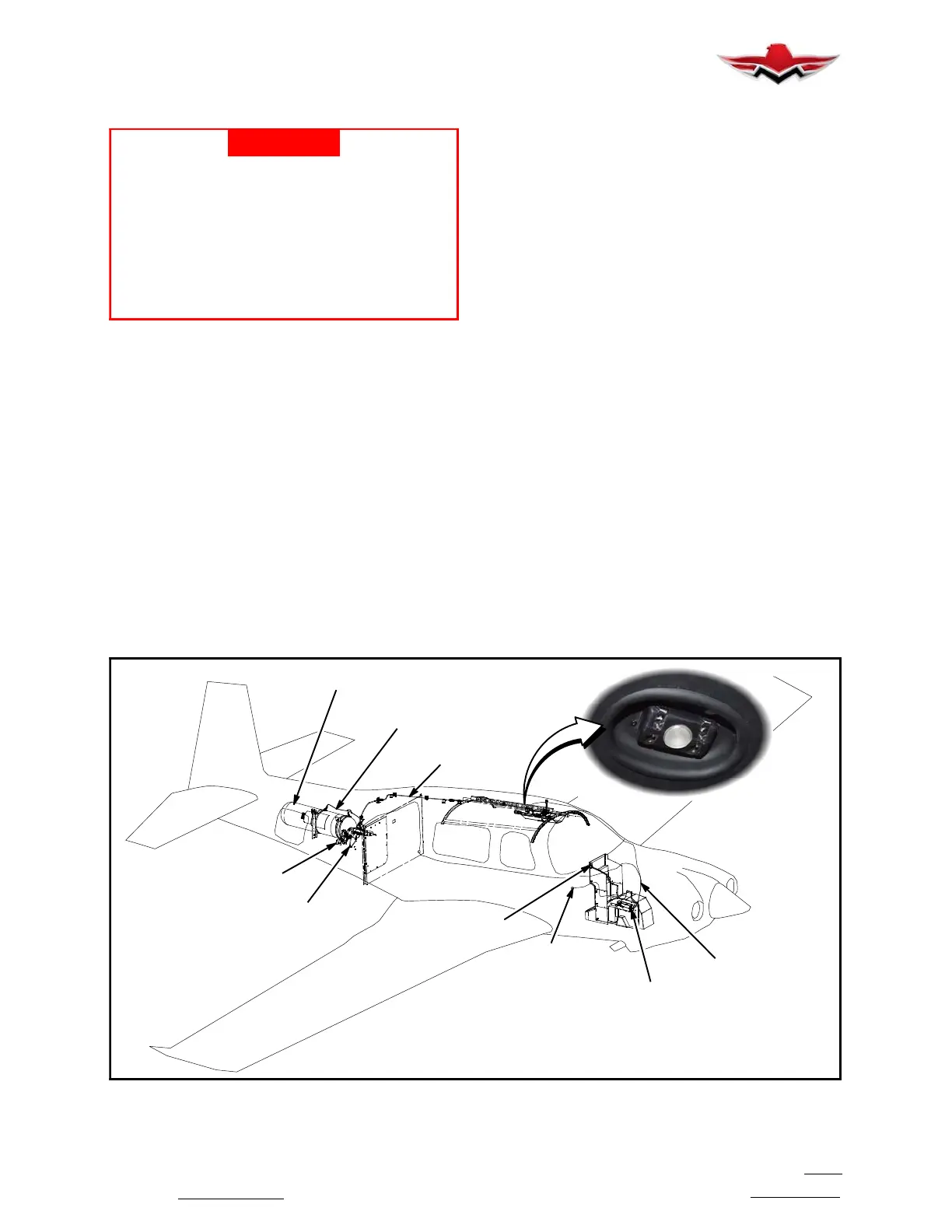
PRECISE FLIGHT OXYGEN SYSTEM
The Precise Flight, Inc. Fixed Oxygen System (“Oxy-
gen System” or “System”), is installed to provide sup-
plemental oxygen for the pilot and passengers. The
System consists of the following:
1. A 77 cu. ft. composite wrapped cylinder mounted
in the aft fuselage tail cone of the aircraft on the right
hand side.
2. An oxygen regulator which is connected to the
bottle and contains:
a. An overpressure discharge
b. A high pressure transducer
3. A Remote Filler Assembly located on the right
hand side of the aircraft, just aft of the baggage door
contains:
a. A service port for filling the Oxygen System, the
system uses a Puritan- Bennett valve.
4. Associated plumbing and fittings
5. A center console panel display and System actua-
tion switch
6. An overhead distribution manifold with low pres-
sure transducer and integrated interior LED dome light
located just aft of the pilots seats and in- front of the
passenger seats in the overhead panel.
7. Breathing devices and flowmeters with cannulas,
or masks Setting the oxygen switch to ON illuminates
the display showing oxygen quantity and energizes the
System to allow oxygen to reach the overhead distribu-
tion manifold. Additionally the System annunciates if
oxygen should be used in the aircraft as well as oxygen
pressure or electrical faults. Four (4) manually oper-
ated oxygen flowmeters can be connected to the oxy-
gen distribution manifold. The flow controls are cali-
brated and adjustable for altitude by the user. The
following flow controls can be one of the following:
S A4 Flowmeters and Standard or Oxygen Conserving
Cannulas - Up to 18,000 ft.
S A4 Flowmeters and Masks (Standard and Micro-
phone) - Up to 25,000 ft.
S A5 Flowmeters and Standard or Oxygen Conserving
Cannulas - Up to 18,000 ft.
S A5 Flowmeters and Masks (Standard and Micro-
phone) - Up to 25,000 ft.
S PreciseFlow Oxygen Conserver with Dual Lumen
Cannula - Up to 18,000 ft.
S PreciseFlow Oxygen Conserver with Masks (Stan-
dard and Microphone) - Up to 25,000 ft.
CIRCUIT
BREAKER
OXYGEN
CONTROLLER
OXYGEN SYSTEM
DISPLAY
WIRE
ROUTING
LOW PRESSURE
LINES
BOTTLE GROUND
STRAP
OXYGEN BOTTLE
REGULATOR ASSEMBLY
OXYGEN
FILLER
HIGH
PRESSURE LINE
DISTRIBUTION
MANIFOLD
(4 Place)
PRECISE FLIGHT OXYGEN SYSTEM
FIGURE 35-1
35-00-00
 Loading...


