MOONEY INTERNATIONAL CORPORATION
M20V SERVICE AND MAINTENANCE MANUAL
Date
MAR 2017
Rev Date
Page
6
35-00-01 PRECISE FLIGHT OXYGEN SYSTEM
COMPONENTS
The Fixed Oxygen System consists of a few simple
components for supplying sufficient oxygen to the crew
and passengers for the Mooney M20V aircraft (see Fig-
ure 35- 3). These components follow:
Oxygen Bottle
1. Stores 77 cu. ft. of Oxygen at 1850 psig Regulator
Assembly
2. Converts the high bottle pressure to a usable 70
psig for cabin distribution. This is actuated through a
latching solenoid assembly with an electrical connec-
tion to the aircraft cockpit. The regulator assembly al-
lows the bottle to be filled through a separate fill port
and a fill gage. The fill gage allows the maintenance
personnel to monitor the fill operation. An overpressure
burst disc is incorporated to dissipate excess pressure
and protect the bottle. A high pressure transducer elec-
trically transmits bottle pressure to the cockpit display.
Oxygen Remote Filler Station
1. Allows for easy filling of the oxygen system and in-
corporates a manual pressure gage for filling, and pre-
flight. Located for convenient access through the bag-
gage door on the left hand side of the aircraft, just
above the floor on the center of the baggage compart-
ment aft wall. An easy access door covers the filler port
to prevent damage to the filler from shifting baggage.
This filler valve uses a standard “Puritan Bennett” oxy-
gen fill valve.
Oxygen Distribution Lines and Electrical Wiring
Connections
1. The oxygen distribution lines allow oxygen to safe-
ly enter the aircraft cabin. The electrical connections al-
low the bottle and oxygen cabin pressure to be trans-
mitted to the cockpit and for cockpit selection of oxygen
in the aircraft cabin.
Oxygen Distribution Manifold
1. Allows the crew and passengers to connect to the
Oxygen System with four (4) quick disconnect fittings
with the capability of sealing oxygen flow to the cabin
when disconnected.
Oxygen System Display and Display- Logic Con-
troller (DLA)
1. The Oxygen System display provides control over
the oxygen delivery to the aircraft cabin. This display
supports an annunciation to indicate when oxygen is to
be used (above 12,000 ft PA) and an indication of cabin
oxygen or electrical actuation fault. The cabin oxygen
flashing fault illuminates if cabin oxygen is not between
60 psig and 85 psig. The electrical actuation fault illumi-
nates if there is an electrical short or open circuit to the
latching solenoid at the regulator. The oxygen control-
ler supports these functions and ensures a short dura-
tion signal to drive the latching solenoid.
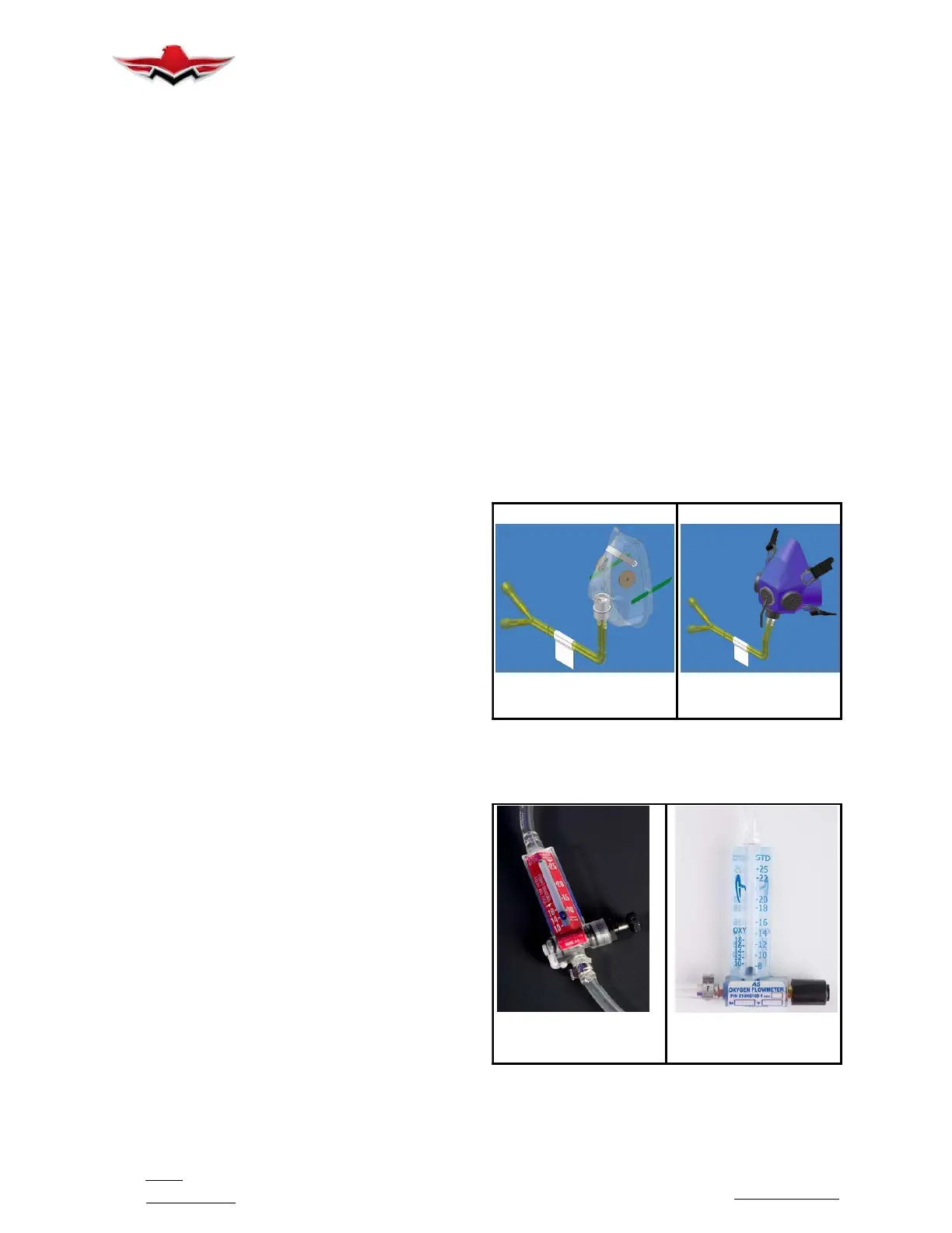
Breathing Equipment
1. The breathing equipment can consist of either
constant flow and/or demand flow regulator breathing
stations. Both use a connection to the distribution man-
ifold. Precise Flight A4 or A5 constant flow devices or
“Flowmeters” indicate the flow of oxygen with an inte-
gral valve to control the quantity of oxygen reaching the
crew or passenger. The PreciseFlow Demand Flow
conservers are calibrated and adjusted by the user for
altitude to supply oxygen to either dual lumen cannulas
up to 18,000ft, or dual sensing masks. The flow indica-
tor on this flow device is labeled with appropriate oxy-
gen flow for increasing aircraft altitude. The constant
flowmeter or demand regulator is attached to the ap-
propriate approved mask or cannula to deliver oxygen
to the crew or passengers (see Figures 35- 2,- 3,- 4)
DUAL SUPPLY
DUAL SUPPLY MASK
STANDARD MASK
W/MICROPHONE
DUAL SUPPLY MASKS
FIGURE 35-2
A4 Constant Oxygen
Flowmeter
A5 Constant Oxygen
Flowmeter
OXYGEN FLOWMETERS
FIGURE 35-3
35-00-01
 Loading...


