MOONEY INTERNATIONAL CORPORATION
M20V SERVICE AND MAINTENANCE MANUAL
Date
MAR 2017
Rev Date
Page
11
Ground Test (Method B)
Method B for checking the calibration is by ground test.
The ground test requires the removal of copilots side
Center Console Trim Panel to gain access to the Dis-
play Logic it Controller (DLA).
-NOTE-
This should be performed during the Cabin
Group Inspection as part of the Annual inspec-
tions. In the case of a progressive Maintenance
Program, this test should be accomplished as
close to once every year, not to exceed
18months.
Use the flowing procedure for the ground test method
for the DLA pressure calibration check:
1. Remove the Pilot Seat if not already removed as
part of the annual maintenance check, cabin group.
2. Remove the RH Center Trim Panel if not already
removed as part of the annual maintenance check,
cabin group to gain access to the DLA. (See Figure
35- 6)
EXISTING
RIVET
WHEELWELL
DISPLAY
LOGIC
CONTROLLER
(DLA)
DISPLAY LOGIC CONTROLLER
FIGURE 35-9
3. Check general condition of the wiring, and DLA.
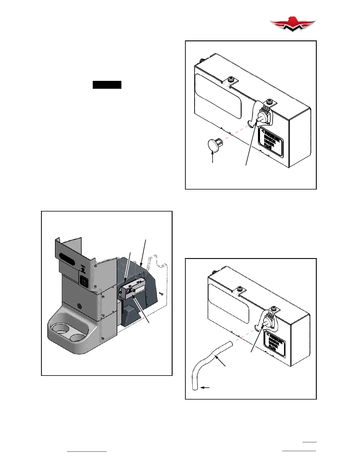
4. Remove the Dust Cover/Plug. (See Figure 35- 7)
PRESSURE
SENSOR
PRY OUT
PLUG
DISPLAY LOGIC CONTROLLER
FIGURE 35-10
5. Using a soft rubber or simulate tube with and Inside
Diameter (ID) of 7/16in, connect one end to the pres-
sure sensor nipple, and the other to the static line on a
Pitot- Static Test system with pump. (See Figure 35- 8)
PRESSURE
SENSOR
7/16” INSIDE
DIAMETER
TO TEST
EQUIPMENT
DISPLAY LOGIC CONTROLLER
FIGURE 35-11
35-00-03
 Loading...


