MOONEY INTERNATIONAL CORPORATION
M20V SERVICE AND MAINTENANCE MANUAL
Page
Date
9
MAR 2017
Rev Date
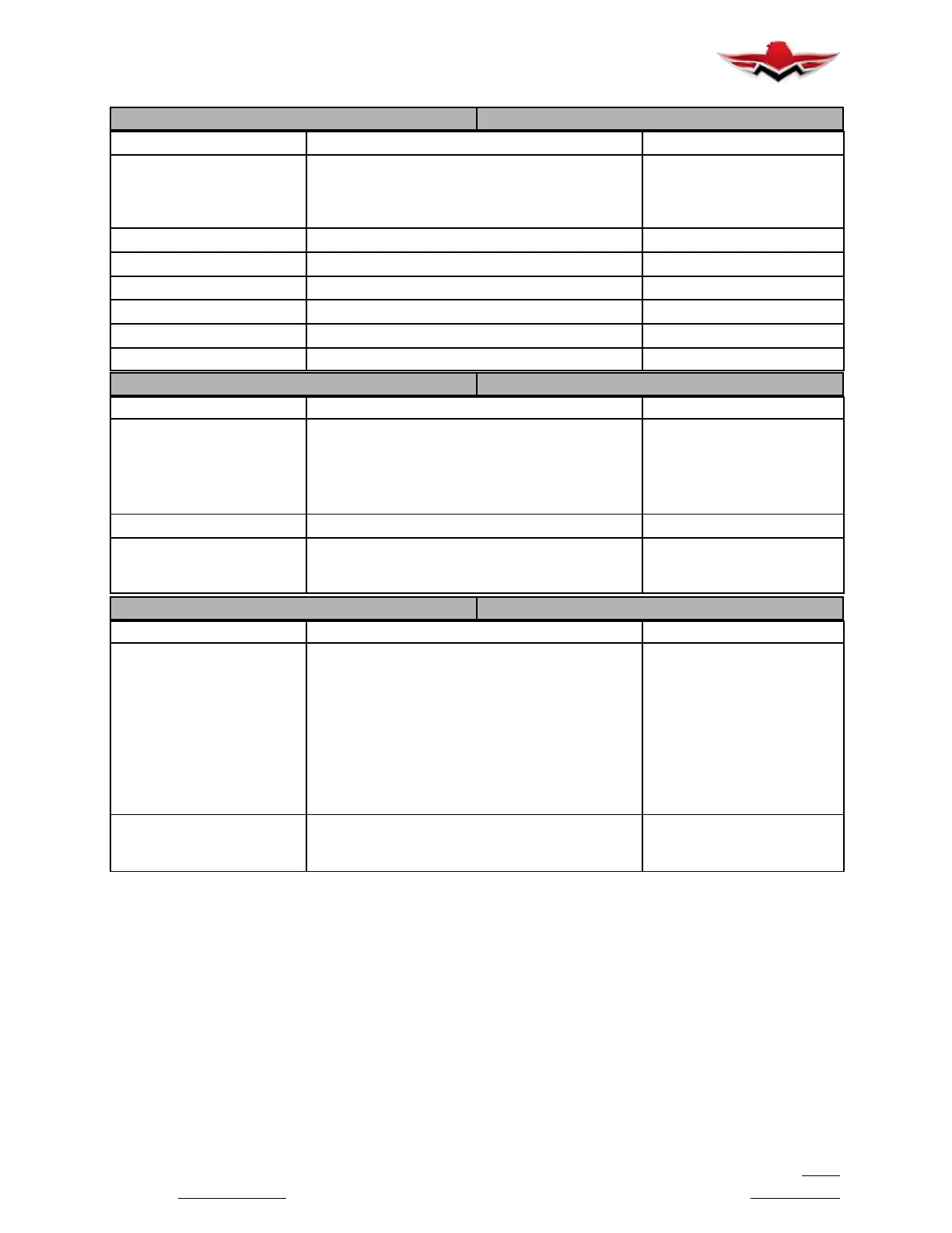
G1000 GFC700 AFCS
GFC700 ACFS System Complete Visual Inspection Aircraft Annual
Flap Discrete Function
Check (
Airworthiness Limita-
tion Maintenance Requirement
(see Chapter 4)
Test the Flap- in- motion discrete inputs to the
G1000 to verify proper operation.
100 Hours or Aircraft Annual
GSA 81 Servos (all) Remove & Replace On Condition
GSA 81 Servos (all) Clean and Apply Grease to Output Gears 1000 Hours or 36 Months
Pitch Bridle Cable Remove & Replace On Condition
Pitch Trim Chain Remove & Replace On Condition
GSM 85 Servo Mounts (all) Remove & Replace On Condition
GSM 85 Servo Mounts (all) Check Slip Clutch Torque (adjust if necessary) 500 hrs or 12 Months
G1000 Lightning Protection
ITEM Description/Procedure Interval
TVS Unit Replacement
Replace the voltage suppressor unit. Refer to
G1000/GFC700 Wiring Diagram
The Standby Attitude Indicator Voltage Suppres-
sor is located behind instrument panel near the
Standby Attitude Indicator harness connector
Replace After Suspected/
Actual Lightning Event
Visual Inspection Complete Visual Inspection Aircraft Annual
Electrical Bonding Test Perform an electrical bonding resistance check of
all G1000 equipment.
100 Hours and After Sus-
pected/Actual Lightning
Event
Engine/Airframe Sensors
ITEM Description/Procedure Interval
SENSORS:
MAP Sensor
Oil Pressure Sensor
Oil Temp Sensor
Tach Sensor
Fuel Flow Sensor
CHT Probes
EGT Probes
TIT Probe
Battery Current Sensor
Remove & Replace - Refer to Specific Section of
the MAC Service & Maintenance Manual.
On Condition
Fuel Tank Quantity Sending
Units - G1000 Fuel Tank
Recalibration
Remove & Replace - New replacement fuel
quantity probe(s) must be re-calibrated.
On Condition
5-10-01
 Loading...


