MOONEY INTERNATIONAL CORPORATION
M20V SERVICE AND MAINTENANCE MANUAL
Date
MAR 2017
Rev Date
Page
12
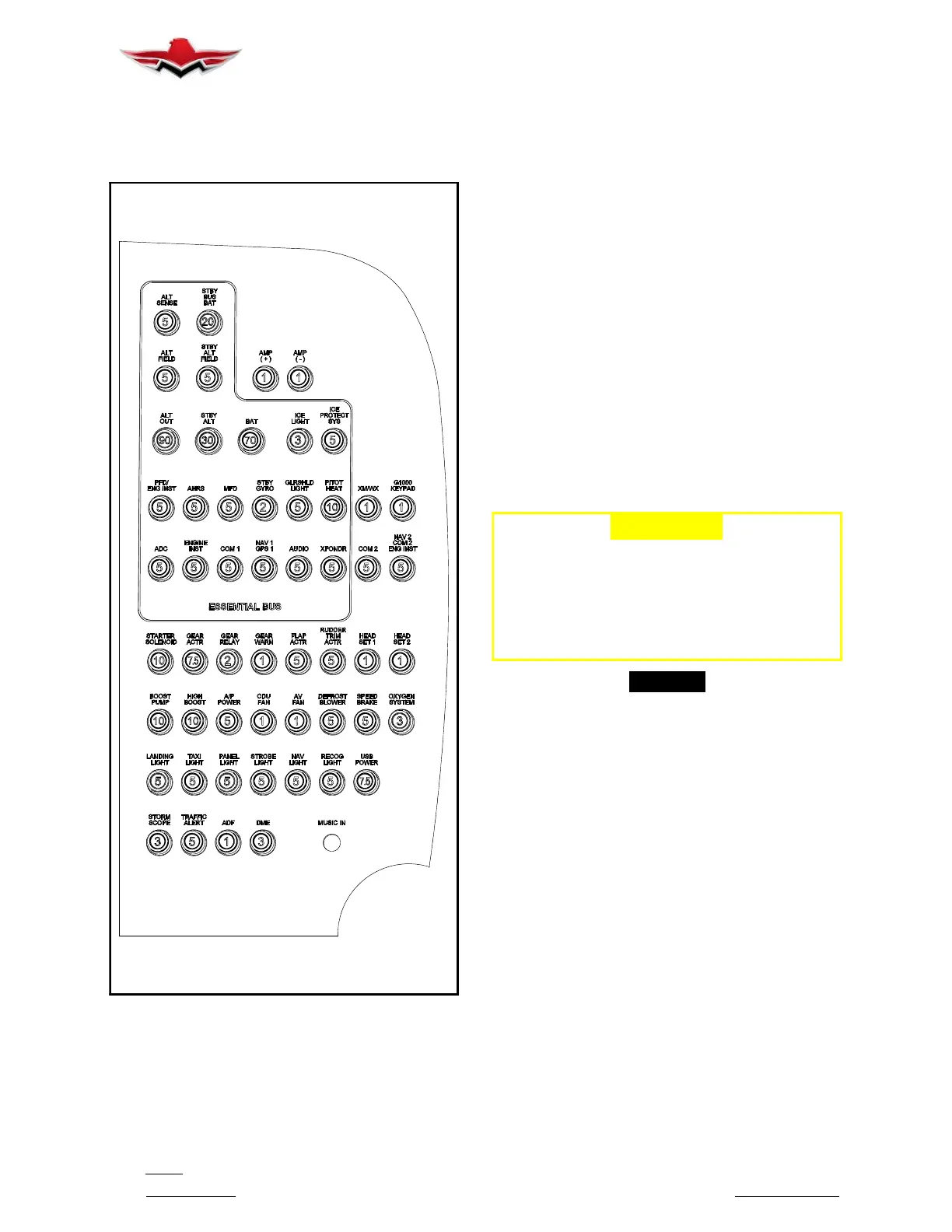
39-10-02 - CIRCUIT BREAKER PANEL
The Circuit Breaker Panel (Figure. 39- 3) is an assem-
bly that can be removed for increased access to com-
ponents for removal and repair.
CIRCUIT BREAKER PANEL (TYPICAL)
FIGURE 39-3
Turn master switch - OFF.
1. To Remove (Figure. 39- 4)
A. Remove glareshield – refer to Section
39- 10- 01.
B. From under dash area remove any cable ties
from circuit breaker harnesses to allow tray to slide out.
C. Remove upper (1) screw from rear upper center
face of circuit breaker panel. Note a clip-nut is installed
on the bracket, keep for re-assembly. Bracket is at-
tached to C/B panel using Click Bond CB200 (Figure.
39- 4).
D. From under C/B, remove lower center (2)
screws. These (2) screws have (2) spacers that will re-
lease and be reused upon assembly. (see Figure
39- 4).
E. Remove lower (1) screw from rear lower corner
face of circuit breaker panel. Note a clip-nut is installed
on the bracket, keep for re-assembly. Bracket is at-
tached to C/B panel using Click Bond CB200 (Figure.
39- 4).
F. Panel should now be free to slide out for repair.
-CAUTION-
USECAREWHENREMOVINGCIRCUIT
BREAKER TRAY ASSEMBLY, CONNECTOR
TABS ON THE RECTIFIER BRIDGE ARE
FRAGILE AND CAN BE BROKEN WITH EX-
CESSIVE FORCE AND BENDING WIRE
CONNECTIONS.
-NOTE-
In some instances, components, other than the
one to be removed, must be removed or at least
some wiring or plumbing disconnected to gain
access to the desired component.
3. Installation.
A. Installation of new instrument or circuit breaker
into panel is accomplished in reverse sequence of re-
moval. Note make sure main connector is fully seated
before mounting hardware is tightened.
39-10-02
 Loading...


