MOONEY INTERNATIONAL CORPORATION
M20V SERVICE AND MAINTENANCE MANUAL
Date
MAR 2017
Rev Date
Page
13
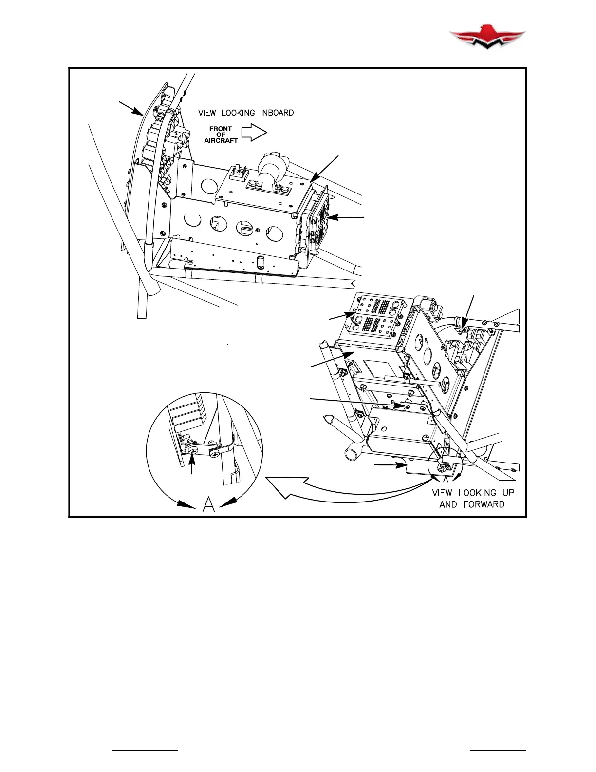
UPPER SCREW (1)
SCREW (x2)
WASHER (x2)
SPACER (x2)
TRAY ASSEMBLY
C/B (EL) PANEL
RACK ASSEMBLY
C/B (EL)
PANEL
MAIN
CONNECTOR
ASSEMBLY
MAIN
CONNECTOR
ASSEMBLY
LOWER
SCREW (1)
CIRCUIT BREAKER PANEL REMOVAL
FIGURE 39-4
3. Installation.
A. Installation of new instrument or circuit breaker
into panel is accomplished in reverse sequence of re-
moval.
B. Insert lexan insulator strip(s) in proper location
to prevent any short circuits.
39-10-03 - CONTROL WHEELS
The aircraft has dual flight controls and can be flown
from either the pilot or co- pilot seat. Each Control
Wheel may contain controls for Trim Adjust, Identifica-
tion Transponder, Autopilot Disconnect/Control Wheel
Switches, Speed Brake, Microphone Switch, Map Light
and Stormscope Refresh, depending on Sales Order
configuration. See next Figures for typical configura-
tions.
With aircraft Master Power Off and batteries discon-
nected, switches and controls may be removed for re-
placement or service by removing retaining screws
from nameplate and then detaching electrical connec-
tions. Remove push button switches by carefully
pulling plastic push button off switch actuator, unscrew-
ing nut from stem and pushing switch through name-
plate. Reinstall switches and controls in reverse order.
Switch/control wire connections may be at switch/con-
trol position or routed from end of Control Yoke Shaft up
39-10-03
 Loading...


