MOONEY INTERNATIONAL CORPORATION
M20V SERVICE AND MAINTENANCE MANUAL
Date
MAR 2017
Rev Date
Page
14
and through left or right grip of Control Wheel. Solder
connections at switch terminals, where applicable,
should be covered with heat shrink tubing.
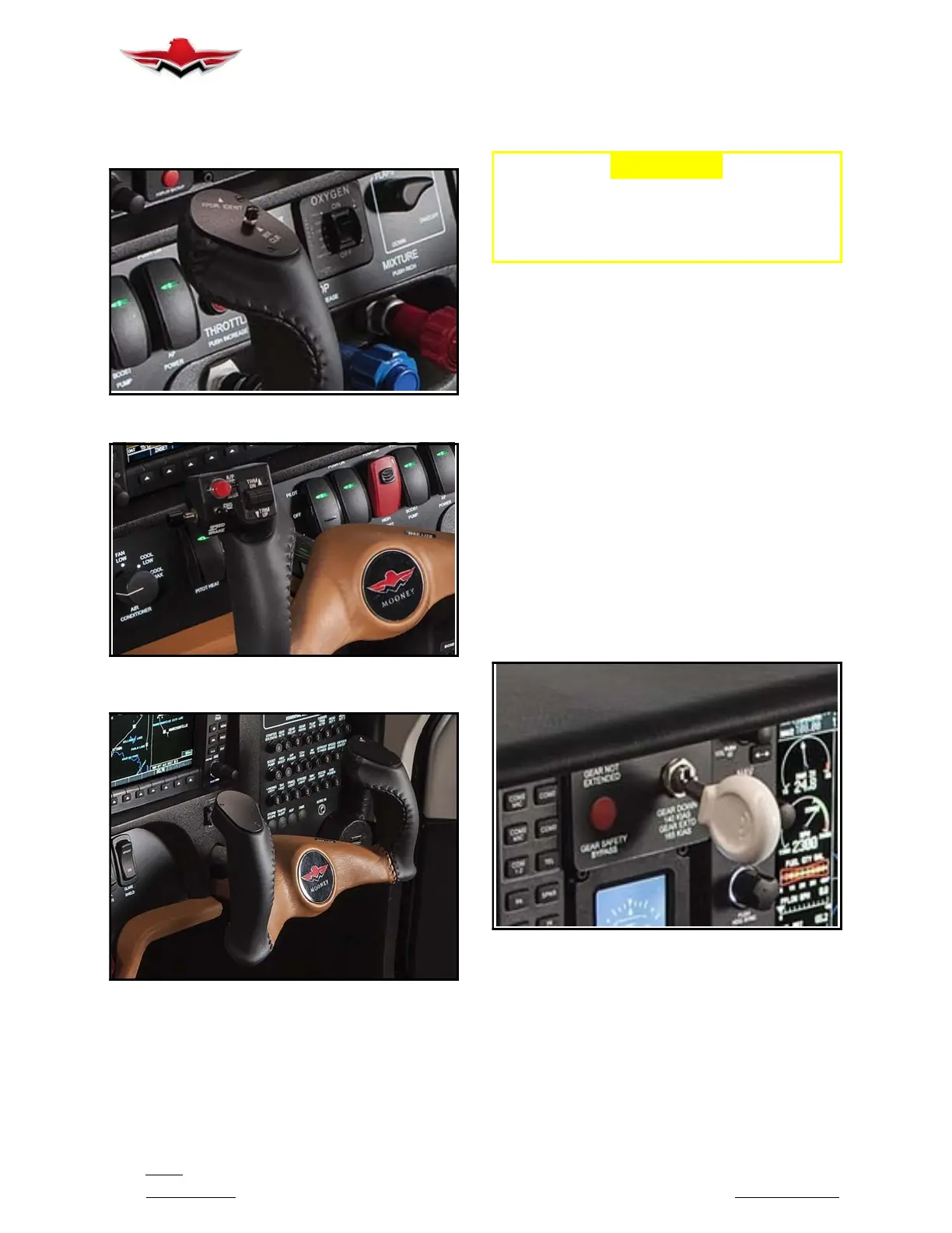
PILOT’S CONTROL WHEEL RH GRIP
FIGURE 39-5
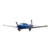
PILOTS CONTROL WHEEL LH GRIP
FIGURE 39-6
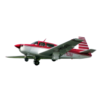
CO- PILOT’S CONTROL WHEEL RH GRIP (TYP)
FIGURE 39-7
39-11-00 - FLIGHT INSTRUMENT PANEL
The flight instrument panel is a shock mounted panel
containing various flight instruments. These instru-
ments vary slightly depending upon options installed.
The panel contains circuit breaker/switches, along with
Master Switch, which control most systems of aircraft.
Refer to Figures 39- 1.
-CAUTION-
Care should be exercised when replacing
wiring or switches to ensure proper align-
ment of terminal connections to prevent
shorting between switches.
Access for maintenance of switches or related wiring is
obtained by removing two attachment screws and
pushing switch forward through panel or by sliding it aft
from panel. There is a common bus bar on some
switches that will require loosening or removal for
switch replacement.
39-11-01 - LANDING GEAR SWITCH
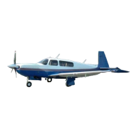
The landing gear switch (Figure 39- 8) is a two position
switch located at the top center, of flight instrument
panel. The wheel shaped knob must be pulled aft prior
to raising or lowering switch to activate landing gear ac-
tuator.
1. Access to the switch for maintenance is from be-
hind the top edge of the instrument panel.
2. Disconnect wire connector attaching switch as-
sembly to harness.
3. Unscrew wheel shaped knob counterclockwise to
remove from stem.
4. Remove nut and washer from face of switch and
push switch through panel.
LANDINGGEARSWITCH&LANDINGGEAR
SAFETY OVERRIDE SWITCH
FIGURE 39-8
39-11-02 - LANDING GEAR SAFETY OVERRIDE
SWITCH
The landing gear safety override switch (with integral
indicator light) is located to the right of landing gear
switch panel (Figure 39- 8). Proper operation of landing
gear safety system will not allow gear to retract below
60 5 KIAS.
39-11-00


 To Next Page