MOONEY INTERNATIONAL CORPORATION
M20V SERVICE AND MAINTENANCE MANUAL
Date
MAR 2017
Rev Date
Page
15
-CAUTION-
Activation of gear safety override switch
while aircraft is on ground may cause landing
gear to retract.
1. Disconnect wire connector (Figure 39- 9), approxi-
mately 10 inches from switch.
2. Loosen nut on stem and hold nut located inside
mounting bracket.
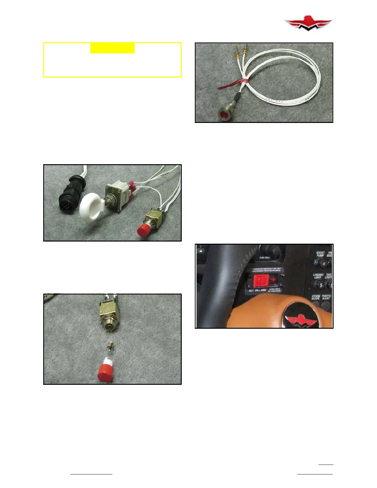
3. The light bulb, 28VAC AT604 (Figure 39- 10) can
be replaced by pulling RED lens off switch assembly.
Light bulb can be removed from socket by gently pulling
with fingertips.
LANDING GEAR SWITCH & LANDING GEAR
SAFETY OVERRIDE SWITCH
(REMOVED FROM PANEL)
FIGURE 39-9
LANDING GEAR SAFETY OVERRIDE SWITCH
(REMOVED FROM PANEL)
FIGURE 39-10
4. The Check Gear Light, located in the lower left corner
of the Landing Gear Nameplate, is not serviceable and
must be replaced as a unit, if defective (Figure 39- 11).
CHECK GEAR LIGHT
(REMOVED FROM PANEL)
FIGURE 39-11
39-11-03 - CLOCK
A Real- Time Clock is integral to the Garmin 1000
Avionics System.
39-12-00 - EMERGENCY LOCATOR TRANSMIT-
TER (ELT) SWITCH
ARTEX ME- 406 ELT
The Artex ME- 406 remote ELT switch (Figure 39- 12)
is located on the Instrument Panel. The location is de-
termined by optional equipment per sales order. The
ELT is located in the tailcone and is accessible by re-
moving radio access panel on right or left side of aircraft
tailcone. The ELT antenna is located on top of tailcone
underneath the fiberglass dorsal fin.
EMERGENCY LOCATOR TRANSMITTER (ELT)
REMOTE SWITCH (ARTEX ME- 406)
FIGURE 39-12
Refer to the Artex web site www.artex.net for latest in-
formation and updates to the information provided in
this service & maintenance manual regarding the Artex
ME- 406 ELT.
In a crash, an acceleration activated crash sensor
(G- switch) turns the ELT “ON” automatically when a
change in velocity (deceleration) of 4.5 fps 0.5 fps is
sensed. Activation is also accomplished by the cockpit
instrument panel mounted remote switch or local
switch on the ELT. To deactivate the ELT, set either
switch to “ON” position and the back to “ARM.”
The ELT does not have an “OFF” position. A jumper be-
tween two pins on the front of the D- sub connector
39-11-03
 Loading...


