MOONEY INTERNATIONAL CORPORATION
M20V SERVICE AND MAINTENANCE MANUAL
Page
Date
5
MAR 2017
Rev Date
51-00-00 - GENERAL
The Mooney M20V is an all metal, low wing airplane.
The fuselage cabin area is constructed of welded 4130
chrome- molybdenum steel tube. The steel tubular
structure is covered with non- structural, composite
shell fastened to tubular structure using stand-off
mounts, rivets, bolts, screw and epoxy.
The tailcone is of semi- monocoque type construction
and is fastened to the tubular structure with structural
bolts.
The wing is a tapered, laminar flow, one piece wing. It is
constructed with a one piece, full length main spar. The
spar is constructed from tapered cap strips (7075 alu-
minum) bolted (huckbolts) to webs (2024 aluminum).
Aluminum ribs connect main spar to aft stub spar and
rear spar. Extruded stringers run full length of wing,
spaced chordwise for strength and skin reinforcement.
The skins are stretch formed, wrap around, 2024- T3
aluminum ranging in thickness from .032 at the tip to
.050 at inboard fuel tanks.
The completed wing assembly is mated to the fuselage
tubular structure during final assembly at the Mooney
facility. Removal of wing from fuselage structure is es-
sential for most over land type transportation.
The empennage is of similar construction to the wing. A
main spar spans entire length of the stabilizer. Ribs
connect main spar to stub and rear spar. A stretch
formed skin wraps around leading edge ribs and at-
taches to rear spar on top and bottom.
The elevators are constructed of formed, aluminum
skins fastened to a spar extrusion at the leading edge
and riveted together at the trailing edge.
The vertical stabilizer is constructed around a fabri-
cated main spar assembly with ribs connecting main
and rear spar. A stretch formed, aluminum skin wraps
around leading edge ribs and is riveted to rear spar on
both sides.
The rudder is constructed of formed aluminum skins
fastened to a spar extrusion at the leading edge and riv-
eted together at the trailing edge.
A three piece, composite belly skin covers underside of
aircraft from exhaust cavity aft to tailcone.
The front seats are installed on rails, which are at-
tached to floorboard and structure beneath floorboard.
The M20V features two rear passenger seat configura-
tions; a split type rear seat, using seat cushions in
molded wells over wing spars and individually reclining
rear seat backs or, a three- place bench seat.
51-10-00 - STRUCTURAL REPAIR - GENERAL
This section outlines structural repair procedures for
the M20V airplane. It is intended to supplement FAA
Advisory AC 43.13- ( ) by showing repair methods spe-
cific to Mooney airplanes.
All structural repairs must be: in compliance with AC
43.13- ( ) unless specific Mooney factory repairs are
recommended, or with the specific approval of a Feder-
al Aviation Administration representative, which is final
authority in all repairs. This manual is for general guid-
ance and has no authorized approval status. The Prod-
uct Support Department, Mooney International Corpor-
ation, Kerrville, Texas, should be consulted for special
repair procedures when repair of damaged structure is
not covered by published instructions.
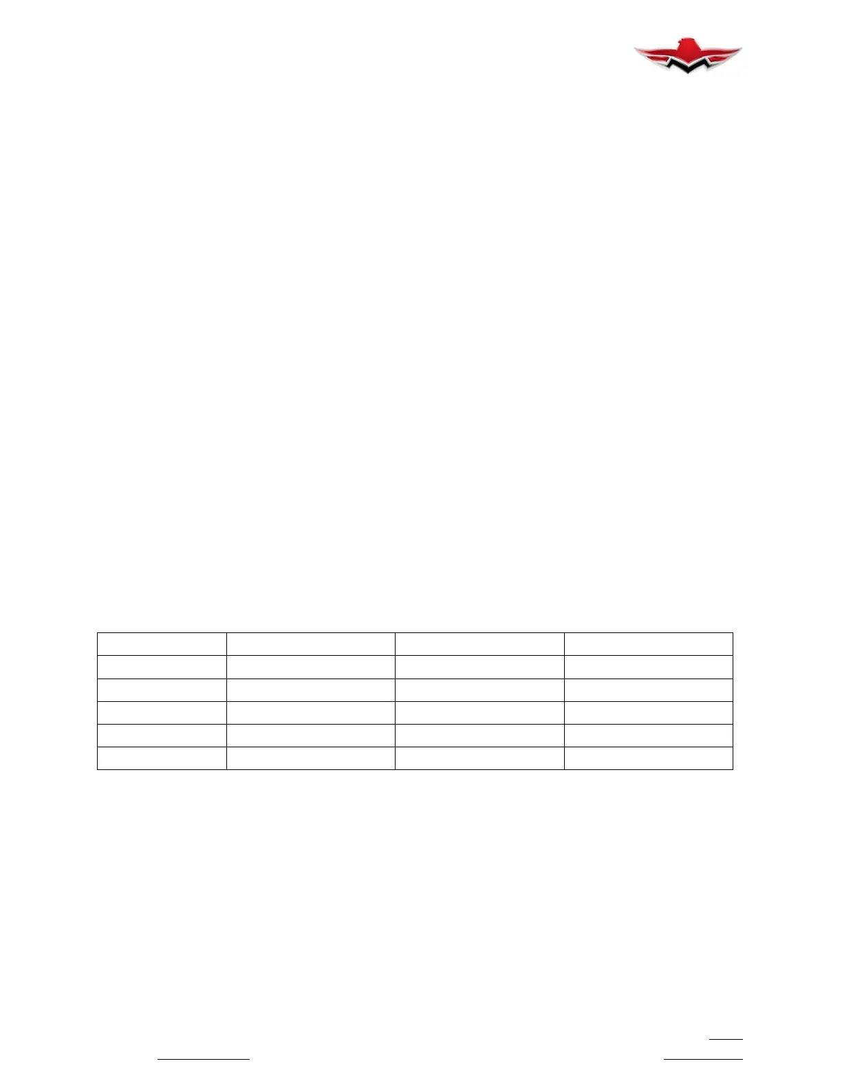
Huck Fastener
Pre- Drill Size Drill Size Hole Limits
2LPH- T5 No. 26 (.147 IN.) No. 20 (.161 IN.) .161 to .1635 IN.
ALPPH- T6 No. 18 (.1695 IN.) No. 13 (.185 IN.) .185 to .187 IN.
R3001- T6 No. 18 (.1695 IN.) No. 13 (.185 IN.) .185 to .187 IN.
2L426H- T5 No. 26 (.147 IN.) No. 20 (.161 IN.) .161 to .1635 IN.
R3007- T6 3/16 (.187 IN.) No. 7 (.201 IN.) .2005 to .2025 IN.
HUCKBOLT HOLE LIMITS
Figure 51- 1
51-10-01 - FASTENER REPLACEMENT
1. HUCKBOLT INSTALLATION. The Huck Lockbolt
is an interference fit fastener used in a rigid joint struc-
ture. A loose or slip fit Huckbolt is unacceptable (Figure
51- 1).
When Huckbolt hole is enlarged beyond above limits
but is straight and round, the hole may be considered
acceptable, provided that Huckbolt cannot be pressed
into hole, with normal hand pressure, to a depth more
than 50 percent of heaviest material being secured.
Check enlarged hole size at both ends. Select proper
Huckbolts to fit the oversize holes.
Oversize Huckbolt holes may be repaired by replacing
2LPH- T5 Huckbolts with ALPPH- T6 Huckbolts or with
NAS 623- 2 screws and NAS 1021 No. 8 Hex- lock nuts
(or equivalent), provided pitch distance is greater than
.56 inches and edge distance is greater than .33 inch-
es. Huckbolts ALPPH- T6 and R3001- T6 may be re-
placed with R3007- T6 Huckbolts as necessary. Con-
sult Product Support Department, Mooney
International Corporation, Kerrville, Texas, for factory
51-00-00
 Loading...


