MOONEY INTERNATIONAL CORPORATION
M20V SERVICE AND MAINTENANCE MANUAL
Page
Date
6
MAR 2017
Rev Date
recommendations when the preceding instructions are
inadequate to accomplish repair.
To compensate for material thickness tolerances,
Huckbolt lengths may be increased by one dash num-
ber from the prescribed length. When a Huckbolt pin of
proper length is not available, use pin of next longer
length.
To adjust grip length, install a cadmium- plated steel
washer .065 inch thick (or a combination of not more
than two washers .065 inch and .032 inch thick) under
Huckbolt collar. The combined thickness of any two
washers shall not exceed .098 inch. Huckbolts or coni-
cal Keystone Lock blind rivet heads may be cocked no
more than .004 inch. Not more than 20 percent of fas-
teners in any pattern, nor more than three fasteners in
succession, may be cocked.
-NOTE-
Where access is limited or for replacement/re-
pair, refer to Figure 51- 2 for permissible
substitutions.
HUCKBOLT
P/N
SUBSTITUTE P/N
(VENDOR)
DESCRIPTION
NAS 1465 or
R3001- T5
HL20- 5 Pin (Hi- Shear)
HL86- 5 Collar
Pin- Protruding
Tension 160 KSI Ftu
NAS 1466 or
R3001- T6
HL20- 6 Pin (Hi- Shear)
HL86- 6 Collar
Pin- Protruding
Tension 160 KSI Ftu
NAS 1475 or
R3014- T5
HL19- 5 Pin (Hi- Shear)
HL94- 5 Collar
Pin- 100 D. Flush
Shear - 95 KSI Fsu
NAS 1476 or
R3014- T6
HL19- 6 Pin (Hi- Shear)
HL94- 6 Collar
Pin- 100 D. Flush
Shear - 95 KSI Fsu
NOTE - HL2086- x- x and HL1994- x- x are P/N’s which include Pins and Collars.
Customer MUST suuply diameter and grip data.
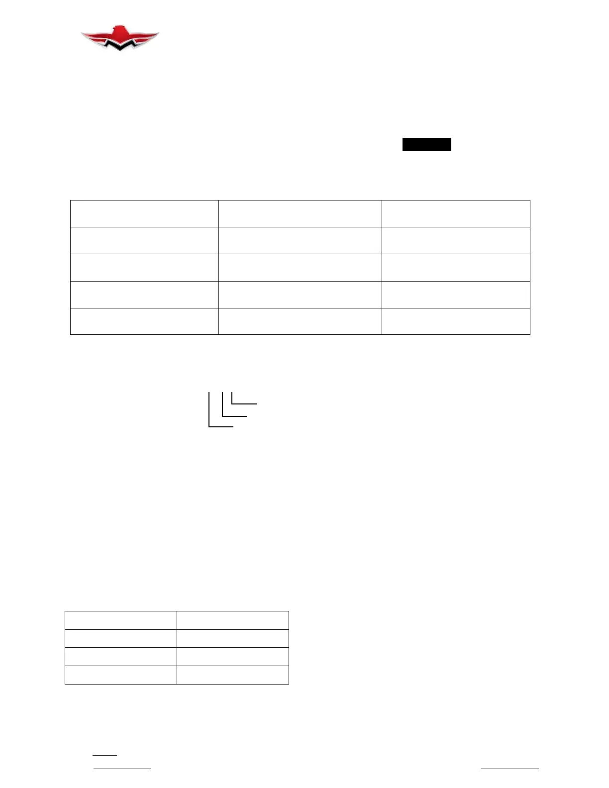
PART NUMBER CODE
HL-5-8
Grip in 1/16ths” (8/16 = 0.500) MAX
Nominal Dia. in 1/32nds” (5/32 = 0.156)
Pin Part number
HUCKBOLT SUBSTITUTION TABLE
FIGURE 51- 2
2. RIVET REMOVAL AND REPLACEMENT.
A. REPLACEMENT- STANDARD SIZE RIVETS,
HOLE OVERSIZE. This repair applies only to original
aluminum alloy, steel, or monel rivets of 1/16, 3/32, 1/8,
and 5/32 inch diameters. Such rivets may be replaced
as noted and limited below and in General Limitations,
when hole only is oversize.
(1) Protruding Head Joint. If edge distance is a
minimum of two times diameter of original rivet, it will be
permissible to drill for and install the next standard size
larger diameter rivet of the same type and material as
original rivet.
RIVET SIZE
MIN. GAUGE
3/32 0.025
1/8 0.032
5/32 0.040
MACHINE COUNTERSINKING LIMITS
FIGURE 51- 3
(2) Machine Countersink Joint, Method I. If edge
distance is a minimum of two times the diameter of the
next standard size larger diameter rivet and sheet
thicknesses involved are within limits specified for ma-
chine countersinking for the next standard size larger
diameter rivet, it will be permissible to drill and counter-
sink for and install the next size rivet of the same type
and material as original rivet (Figure 51- 3).
(3) Machine Countersink Joint, Method II. If edge
distance is a minimum of two times the diameter of the
original rivet, it will be permissible to drill for and install
the next standard size larger diameter rivet of the same
type and material as original rivet. Do not re-machine
the countersink. After installation, mill excess head
height flush with surface.
(4) Dimpled Joint. If edge distance is a minimum
of two times the diameter of the original rivet, it will be
permissible to drill for and install the next standard size
larger diameter rivet of the same type and material as
original rivet. Do not re-dimple. After installation, mill
excess head height flush with surface. This method is
subject to same limitations as paragraph 2, A (3).
51-10-01


 To Next Page
 Loading...