MOONEY INTERNATIONAL CORPORATION
M20V SERVICE AND MAINTENANCE MANUAL
Page
Date
7
MAR 2017
Rev Date
B. REPLACEMENT- STANDARD SIZE RIVETS,
HOLE AND COUNTERSINK OR DIMPLE OVERSIZE.
This repair applies only to original countersunk head
aluminum alloy rivets of 1/16, 3/32, 1/8, and 5/32 inch
diameters. Such rivets may be replaced (as noted and
limited below) when the hole and countersink or dimple
is oversize.
(1) Machine Countersink Joint. If edge distance
is a minimum of two times the diameter of the next stan-
dard size larger diameter rivet and countersink depth is
not beyond thickness of countersunk sheet, it will be
permissible to rework according to paragraph 2, A (3).
(2) Dimpled Joint. If edge distance is a minimum
of two times the diameter of the next standard size di-
ameter rivet and all parts are dimpled, it will be permis-
sible to rework the smaller dimples to a size to match
the oversize dimple and install the next standard size
larger diameter rivet of the same type and material as
original rivet. Dimples in (7075- T6) must be hot formed
when reworked.
(3) Combined Countersink and Dimpled Joint. If
edge distance is a minimum of two times the diameter
of the next standard size larger diameter rivet, it will be
permissible to rework the smaller countersink or dimple
to a size to match the oversize dimple or countersink
and install the next standard size larger rivet according
to paragraph 2, A (4). Dimples in 7075- T6 must be hot
formed when reworked.
C. RIVET HEAD TOLERANCE.
(1) A rivet head will be considered open if .001
feeler gauge can be inserted between head of flush or
protruding head rivet and top skin.
The top of a flush head rivet must not be below skin sur-
face in which it is installed by a dimension of more than
.004.
D. RIVET HOLE TOLERANCE.
(1) An enlarged hole is defined as having an in-
ternal diametric dimension, in any direction, which ex-
ceeds the sum of the drill diameter normally used, plus
ten percent of the diameter of the rivet shank.
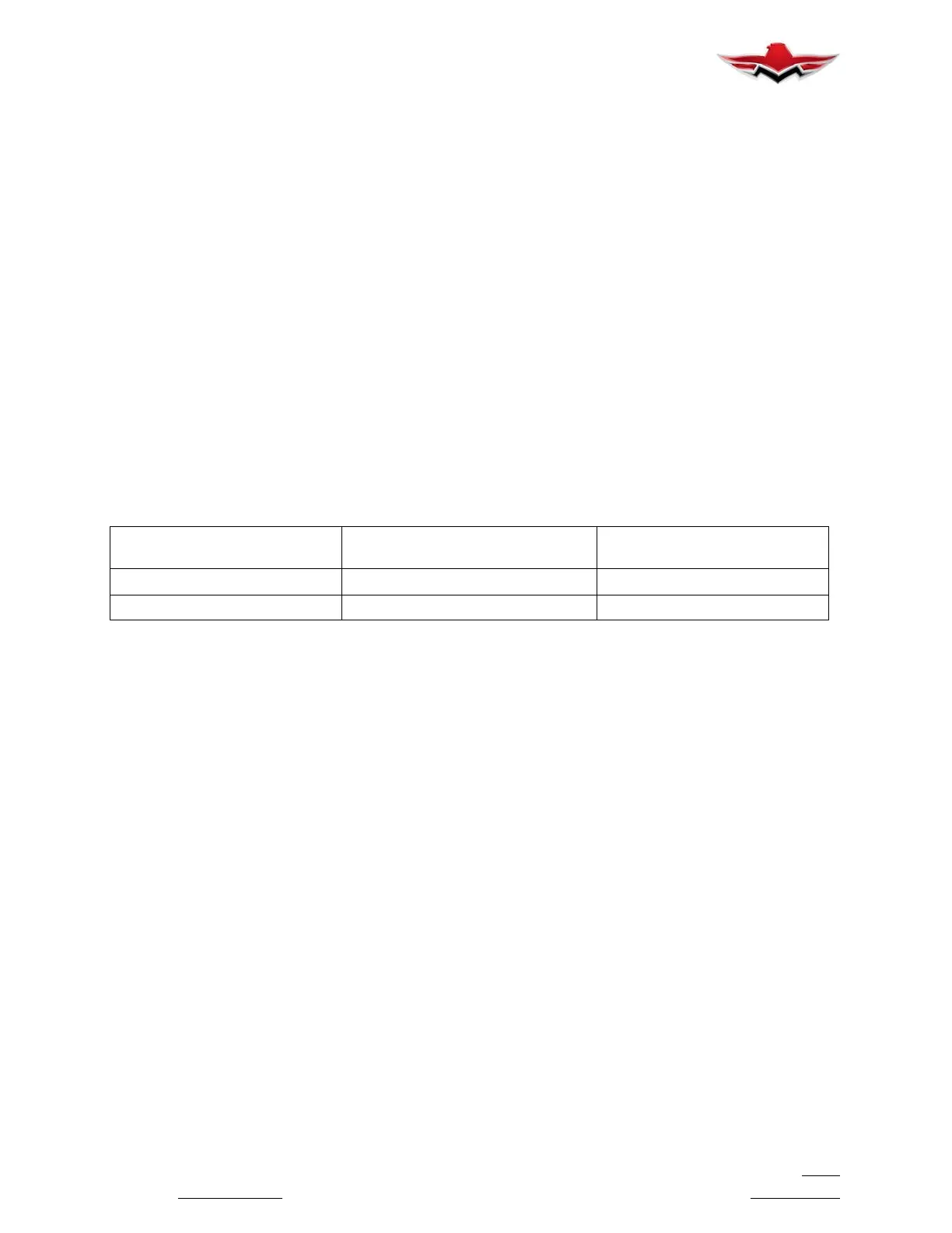
(2) Figure 51- 4 specifies the maximum accept-
able diametric dimensions for various rivet sizes that
occur in multiple layer assemblies which are “drilled on
assembly”.
NOMINAL
RIVET SIZE
MAX. ACCEPTABLE
DRILL SIZE
DIAMETRIC DIMENSION
AN470AD3 or AN426AD3 #40 (0.098 dia.) 0.108 in.
AN470AD4 or AN426AD4 #30 (0.1285 dia.) 0.141 in.
MAXIMUM ALLOWABLE DIAMETRIC DIMENSIONS
FIGURE 51- 4
(3) When a hole becomes enlarged beyond ac-
ceptable diametric limit and the prescribed rivet cannot
be used, the next larger diameter rivet may be used if:
(a) four- diameter (4D) rivet spacing is maintained and
(b) two- diameter (2D) edge distance is maintained.
3. BLIND RIVET INSTALLATION. Ordinarily, where
rivet bucking is impossible, cherrymax (CR- 3212 and
CR- 3213) rivets may be substituted for AD rivets to re-
pair skins and structural members. However, consult
Mooney International Corporation, Product Support
Department or a representative of the Federal Aviation
Administration before using blind- type or hollow rivets
in primary structure.
Check existing rivet hole size before installing blind riv-
ets. When hole is marginal, use next larger size rivet to
assure firm attachment.
4. “AN”- BOLT, NUT AND WASHER INSTALLA-
TION. To compensate for material thickness toler-
ances, the length of AN bolts may be increased or de-
creased by one dash number from prescribed length.
NAS1149 regular washers and NAS1149 thin washers
may be used interchangeably for proper bolt and nut
installation.
One regular washer or one thin washer may be added
to any bolt installation. Washers may be used under the
bolt head and/or under the nut. MS21044 and
MS21045 nuts may be used interchangeably. The
MS21045 nut is acceptable for higher operating tem-
perature installations.
5. HI- SHEAR RIVET INSTALLATION. When a hi-
shear rivet pin of the prescribed length is not available,
the next longer length pin may be used with cadmium-
plated steel washers to adjust pin grip length. The com-
bined washer thickness shall not exceed .096 inch.
6. MS20470- AD4 or MS20426- AD4 rivets may re-
place spot welds in aluminum structures, (1) per spot.
Head side and/or double flush requirements deter-
mined by form, fit & function of assembly.
51-11-00 - RESERVED
51-12-00 - FUSELAGE REPAIR
51-12-01 - TUBULAR STRUCTURE REPAIR
Check tubular structure annually for corrosion and
damage. Refer to Service Bulletin M20- 208( ). Interior
panels may require removal to gain access to areas
which are difficult to inspect.
Refer to AC 43.13- ( ) for general, tubular frame repair
procedures. Warped or bent tube members can often
be straightened; however, all surrounding welds should
be dye checked for cracks after tube straightening.
51-11-00
 Loading...


