MOONEY INTERNATIONAL CORPORATION
M20V SERVICE AND MAINTENANCE MANUAL
Date
MAR 2017
Rev Date
Page
10
CLIP/PIN ASSY
HITCH PIN
HANDLE
CR3213- 4- 2
RIVET
(2 PLC)
LANYARD
(ORIENTATION NOT
CRITICAL)
CR3213- 4- 3 RIVET
AN960- 4 WASHER (2)
(1 UNDER RIVET HEAD &
1ONBACKSIDEOFHANDLE)
MS20470- 4 RIVET (OPT)
BAGGAGE DOOR LATCH MECHANISM
FIGURE 52- 5
52- 60- 00 - ENTRANCE STEPS
There two type of entrance steps installed on the M20V
aircraft. One type is a fixed step which is permanently
attached, and the other is an (optional) removeable
type that can be removed and stowed.
-NOTE-
A Log Book entry is required each time the re-
movable step is removed or replaced.
REMOVABLE STEPS (IF INSTALLED)
Aircraft equipped with removable steps may have it
removed or installed by a certified aircraft mechanic.
If the steps are installed decrease the true airspeed
at normal cruise power setting by approximately 1- 2
KTAS.
To remove/install step:
A. Loosen belly panel camlocs and remove panel to
access removeable step mounting hardware.
B. Remove mounting hardware attaching step to re-
tainer mount and slide step outward.
C. Insert plug assembly
into retainer and mount with
original hardware. Torque to proper values shown in
section 5- 20- 01.
D. Install belly panel and camlocs.
REMOVE BELLY
PANEL
REMOVING BELLY PANEL
FIGURE 52- 6
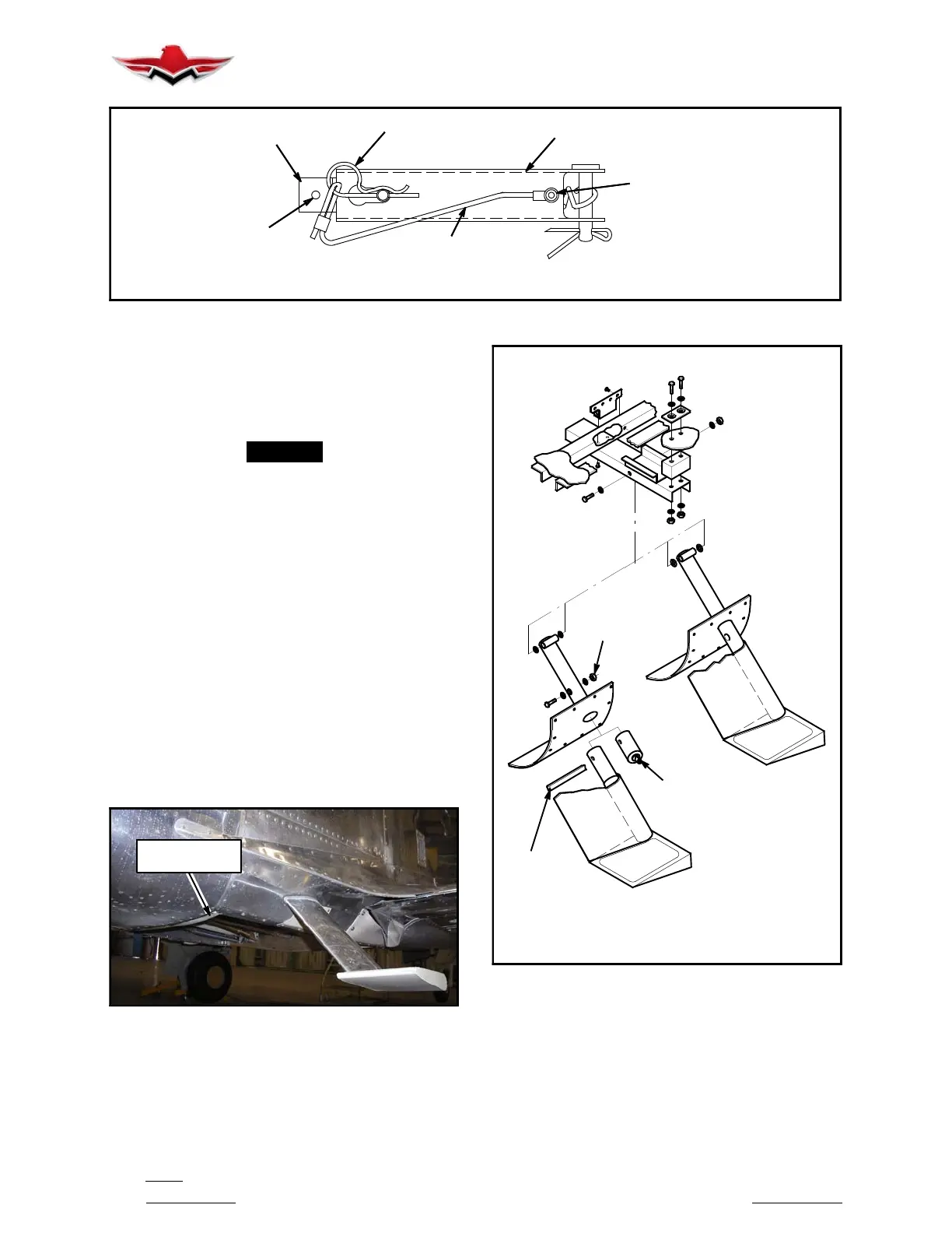
FIXED
REMOVABLE
STEP
STEP
MOUNTING
HARDWARE
PLUG
EXTRUSION
RH SHOWN
LH OPPOSITE
REMOVABLE STEP ATTACHING HARDWARE
FIGURE 52- 7
52-60-00
 Loading...


