MOONEY INTERNATIONAL CORPORATION
M20V SERVICE AND MAINTENANCE MANUAL
Date
MAR 2017
Rev Date
Page
5
55-00-00 - GENERAL
The model M20V empennage assembly is a variable
incidence tail- plane consisting of a horizontal and ver-
tical stabilizer built as a unit (Refer to Chapter 53 for at-
tachment of empennage to fuselage).
The horizontal and vertical stabilizer are constructed of
formed sheet metal ribs attached to a forward and aft
spar assembly covered with stretch- formed skins. The
horizontal stabilizer has a stub spar that spans a por-
tion of stabilizer.
The elevator and rudder are constructed from an ex-
truded leading edge spar assembly covered with
stamped- formed skins. The elevators have a fixed tab
between skins that run full length of trailing edge.
The elevators and rudder have balance weights per-
manently installed for stabilization during flight.
9
9
8
7
9
8
9
8
5
9
8
8
7
11
12
7
6
4
3
2
9
1
10
9
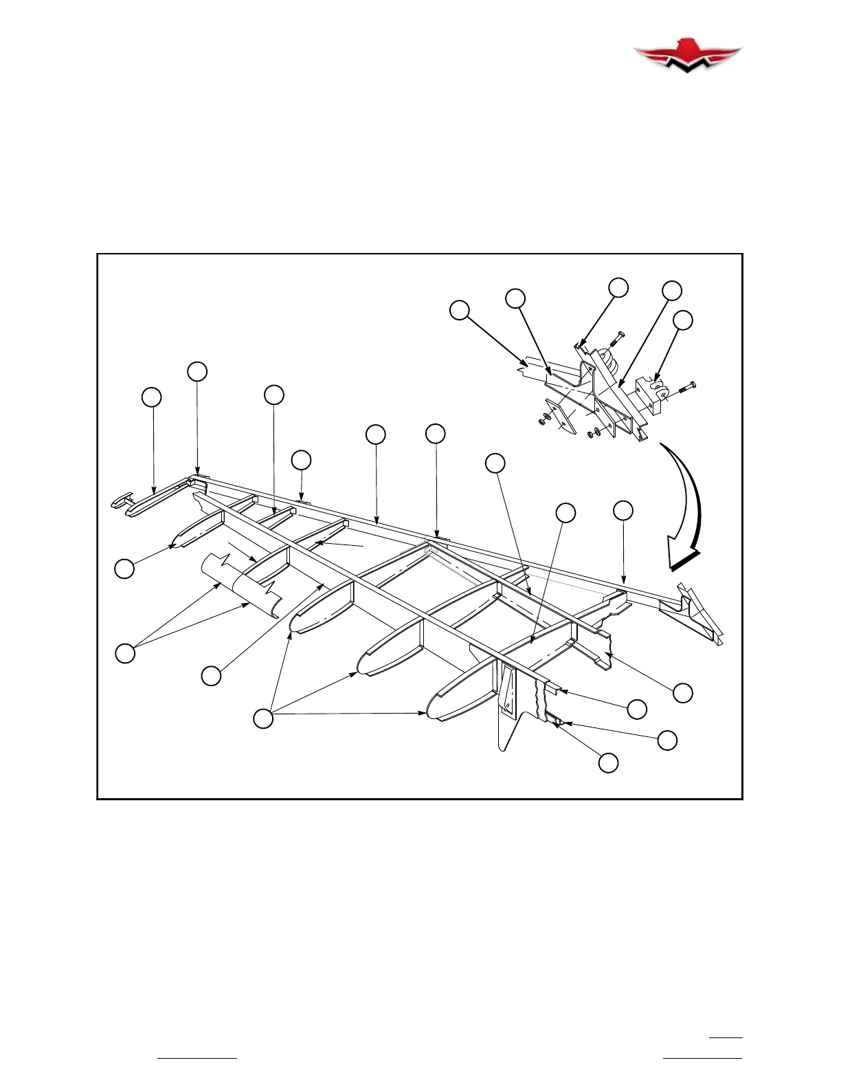
HORIZONTAL STABILIZER
FIGURE 55- 1
55-10-00 - HORIZONTAL STABILIZER
The main spar assembly (1) (Figure 55- 1) is formed
from aluminum sheet into a channel. Angle doublers (2,
3 and 4) are formed and riveted to main spar (1) through
spar web section. Stub spar (5) is a channel formed
from aluminum sheet reinforced with a joggled channel
(6) at center section. Rear spar (7) is an extrusion, at-
taching to aft end of ribs, and contains hinge fittings (8)
for the elevators.
The ribs (9) are assembled in sections to the front and
rear face of each spar assembly to form the air foil.
Stretch- formed skins (10) are fastened to ribs, spars
and doublers to form complete horizontal stabilizer
structure.
The aft vertical fin spar (11) is attached to horizontal
stabilizer structure through bracket (12) which is fas-
tened securely to stabilizer rear spar assembly (7) (Fig-
ure 55- 1).
55-00-00
 Loading...


