MOONEY INTERNATIONAL C ORPORATION
M20V SERVICE AND MAINTENANCE MANUAL
Date
MAR 2017
Rev Date
Page
6
55-10-01 - HORIZONTAL STABILIZER -
REMOVAL
The fairing located on tailcone, covering gap between
tailcone and empennage assembly , will require remov-
al to gain access to empennage attac
hing hardware.
Section 53-40-02 describes attaching points for em-
pennage assembly. Refer to this section for the remov-
al of empennage assembly from airplane.
55-10-02 - HORIZONTAL STABILIZER -
INSTALLATION
Refer to Section 53-40-02 for installation.
A
DETAIL “A”
1
5
4
4
5
2
1
1
5
3
6
3
4
6
6
8
7
6
1
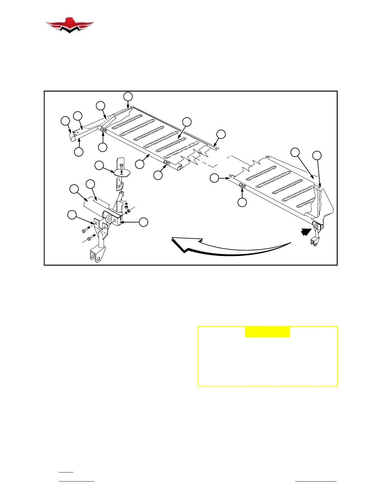
ELEVATOR
FIGURE 55- 2
55-20-00 - ELEVATOR
Elevators on the model M20V consist of left and right
hand assemblies attached, through ball bearing fittings
(1), to rear spar of horizontal stabilizer (Figure 55- 2).
The elevator control horn (2) is connected to inboard
leading edge of each elevator (R.H. and L.H.). Both
control horns are then connected to elevator flight con-
trol bellcrank. The full length trim tab (3) may not be re-
adjusted from factory installed setting. This is factory
set at 7
down.
The elevator skins (4) are stamped- formed for upper
and lower surface of elevator. There are no ribs in ele-
vator between inboard and outboard ribs. The skins are
attached to leading edge extrusion (5) and ribs (6) with
blind rivets. Each formed corrugation is matched on top
and bottom skins and rivets are installed for strength
and rigidity through each corrugation.
A lead balance weight (7) is installed in each elevator
tip with sc
rews (8) (Figure 55- 2). See Section 27-91-00
for balancing procedures on elevators.
55-20-01 - ELEVATOR - REMOVAL
Remove AN3 bolts from each control horn and push-
pull tube bearing, then remove AN3 bolts and hardware
from each hinge fitting on both elevators.
55-20-02 - ELEVATOR - INSTALLATION
-CAUTION-
Each new, repaired or repainted elevator
should be checked for balance per Section
27-91-00.
The elevators are installed in reverse order
of removal. Nominal torque values for AN3
bolts are to be used (see Section 5-20-01
for torque table.)
55-30-00 - VERTICAL STABILIZER
The main spar assembly (1) (Figure 55- 3) is formed
from aluminum sheet. Formed angle doublers (2) are
nested inside main spar channel and riveted to spar
web. Rear spar (3) is an extrusion used to attach aft end
of sectioned ribs (4). Stub spar (5) is also formed from
sheet aluminum. A doubler channel (6) is attached to
vertical stabilizer stub and stub spar of horizontal stabi-
lizer. This attach channel is securely bolted to stinger
55-10-01
 Loading...


