MOONEY INTERNATIONAL CORPORATION
M20V SERVICE AND MAINTENANCE MANUAL
Date
MAR 2017
Rev Date
Page
7
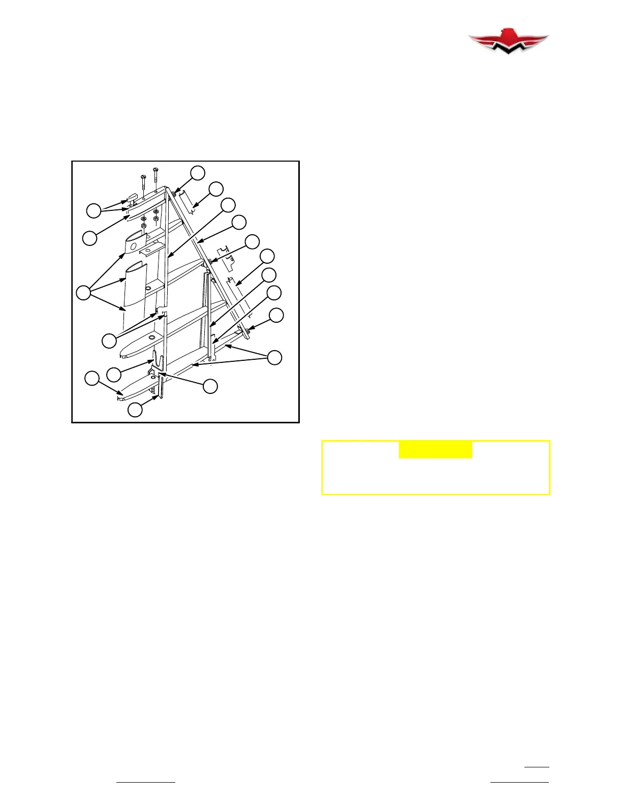
bulkhead brackets. The main spar doublers and angles
(7, 8 and 9) provide attach points for stinger and hori-
zontal stabilizer spar (Figure 55- 3).
Skins (10) are stretch- formed in 2 sections and riveted
to ribs and spar.
The rudder attach fittings (11) are mounted to rear spar
extrusion to attach rudder (12).
8
4
11
6
5
12
11
3
1
12
11
4
13
10
2
4
7
9
VERTICAL STABILIZER ASSEMBLY
FIGURE 55- 3
55-30-01 - VERTICAL STABILIZER - REMOVAL
The vertical and horizontal stabilizers are removed as a
unit with stinger assembly. Remove fairing located on
tailcone which covers gap between tailcone and em-
pennage. Section 53-40-02 describes attaching
points
for complete empennage assembly. Refer to this sec-
tion for removal of empennage assembly from airplane.
55-30-02 - VERTICAL STABILIZER - INSTALLA-
TION
Refer to Section 53-40-02 for installation.
55-40-00 - RUDDER
The rudder on the model M20V is of similar construc-
tion as the elevator with stamped- formed skins (1)
(Figure 55- 4) riveted to an extruded leading edge (2)
and riveted together at trailing edge. The rudder lower
skins (3) are drop hammer formed left and right halves,
riveted to upper skins, rib assembly (4) and at leading
and trailing edge. A stiffener (5) is to support lower rud-
der ball bearing hinge fitting (6). A weather seal (7) is
included in the assembly.
The rudder control horn (8) is attached with center
hinge fitting (9) to rear flange of front spar at junction of
lower rib assembly (10). A brace arm on horn assembly
is attached to fitting (11) on lower rib (10).
The upper hinge fitting (12) is attached to rear flange of
front spar just under top rib assembly (13) and balance
weight (14), (Figure 55- 4).
Balance weight (14) is ins
talled with eight screws (15).
See section 27-91-00 for balancing procedures on rud-
der. Balance weight (16) is installed with two bolts.
55-40-01 - RUDDER - REMOVAL
Remove AN3 bolt from control horn and push- pull tube
bearing, then remove three AN3 bolts and hardware
from each hinge fitting. Disconnect electrical connec-
tions per paragraph 33-41-03, 2, A thru D.
55-40-02 - RUDDER INSTALLATION
-CAUTION-
Each new, repaired or repainted rudder
should be checked for balance per section
27-91-00, prior to installation.
The rudder is i
nstalled in reverse order of removal.
Nominal torque values for AN3 bolts are to be used.
(See Section 5-20-01 for torque table).
55-30-01
 Loading...


