MOONEY INTERNATIONAL C ORPORATION
M20V SERVICE AND MAINTENANCE MANUAL
Date
MAR 2017
Rev Date
Page
10
57-40-00 - ATTACH FITTINGS
Refer to Section 57-00-01 for wing fuselage attach-
ment.
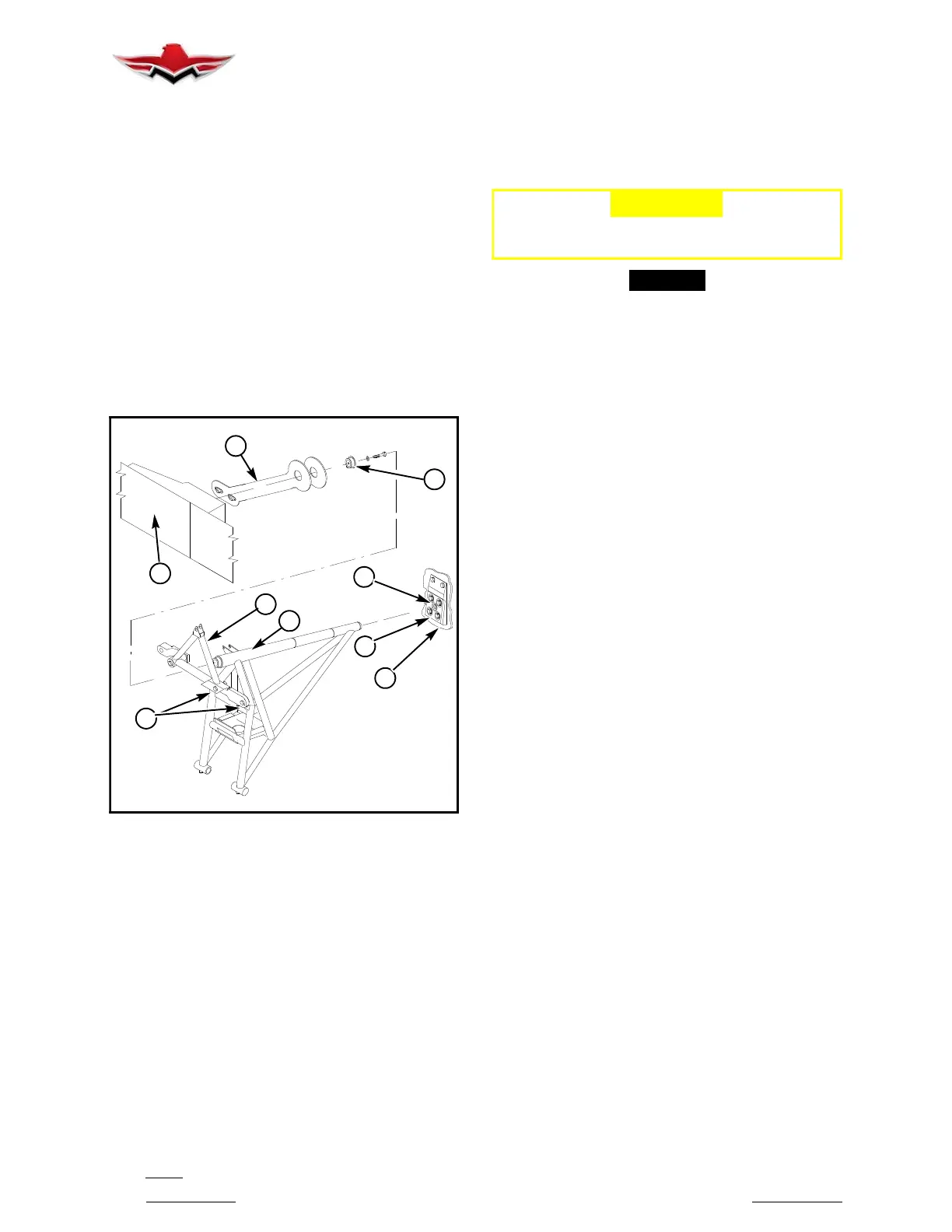
57-40-01 - LANDING GEAR ATTACH POINTS
The main landing gear assembly is a welded, heat-
treated, 4130 chrome molybdenum steel assembly.
The leg assembly (1) (Figure 57- 6), is supported at for-
ward end by tension strap fitting (2) attached to wing
main spar assembly (3) and provides one of the hard
points for main landing gear assembly. The leg assem-
bly (1) is supported at the rear by a bracket (4) attached
to stub spar assembly (5). The main landing gear truss
assembly (6) also attaches to tension strap fitting (2) on
main spar. The brass bearing (7) (insert) should be in-
spected at any scheduled maintenance action for wear
(refer to Chapter 5 - Time Limits/Maintenance
Checks).
7
2
3
8
5
4
8
6
1
MAIN LANDING GEAR ASSEMBLY ATTACH
POINTS
FIGURE 57-6
Grease fittings (8) are installed at pivot points of main
landing gear assembly for lubrication per Chapter 5.
The steerable nose gear mounts to the cabin tubular
steel frame.
-CAUTION-
No welding repairs are approved for the main
landing gear assembly.
-NOTE-
Heat treated components should NOT be re-
paired; replace them.
57-50-00 - FLIGHT SURFACES
Refer to Section 27-90-00 for flight control surface bal-
ancing procedures.
57-50-10 - FLAPS
Refer to Section 27-50-00 for maintenance and rigging
procedures.
The flap actuator jack shaft is connected by a push-
pull, rod end, bearing to flap actuator bracket (1) (Fig-
ure 57- 7) located just inboard of inboard hinge (2). All
three hinges (2) and (3) are faired (4) to reduce drag.
Internal structure of flaps consists of: leading edge ex-
trusion (5), trailing edge stiffener (6), ribs (7) and top
and bottom skins (8). These components are riveted to-
gether into a left hand and right hand assembly.
57-50-11 - FLAP REMOVAL AND INSTALLATION
Refer to Section 27-50-00 for removal and installation
procedures.
57-50-20 - AILERONS
Refer to Section 27-10-00 for maintenance and rigging
procedures.
The ailerons are of all metal construction. The main
spar (1), (Figure 57- 8), is attached to rear spar (2)
through ribs (3). These components are riveted togeth-
er and top and bottom skin (4) and (5) are riveted to this
sub- assembly. To complete control surface, hinges (6)
and balance weights (7) are installed. The weights (7)
are bolted (10) through an outboard rib (8) and bracket
(9) on each aileron assembly.
57-40-00
 Loading...


