MOONEY INTERNATIONAL CORPORATION
M20V SERVICE AND MAINTENANCE MANUAL
Date
MAR 2017
Rev Date
Page
6
1. Cut and remove the safety wire (if installed) on the
propeller mounting studs.
-WARNING-
Make sure the sling is rated up to 800 Lbs.
(363 KG) to support the weight of the propeller
assembly during removal.
2. Support the propeller assembly with a sling.
Supporting the propeller with the sling may be delayed
until all but two mounting studs and washers have been
removed.
If the propeller will be reinstalled and it has been dy-
namically balanced, make an identifying mark (with a
felt- tipped pen only) on the propeller hub and a match-
ing mark on the engine flange to make sure of proper
positioning of the propeller during re- installation. This
will prevent dynamic imbalance.
-CAUTION-
Discard the propeller mounting nuts and
washers if they are damaged or corroded, or
when the propeller is removed for overhaul.
3. Remove the six 1/2 inch mounting nuts.
-NOTE-
If the propeller is removed between overhaul in-
tervals, mounting studs, nuts and washers may
be reused if they are not damaged or corroded.
-CAUTION-
Remove the propeller from the mounting flange
with care to prevent damaging the propel ler
mounting studs.
4. Using the support sling, remove the propeller from
the mounting flange.
61-00-20 - PROPELLER INSTALLATION
DOWEL
PIN
DOWEL
PIN
R61- 4
HARTZELL 3 BLADE PROPELLER INDEXING
FIGURE 61- 2
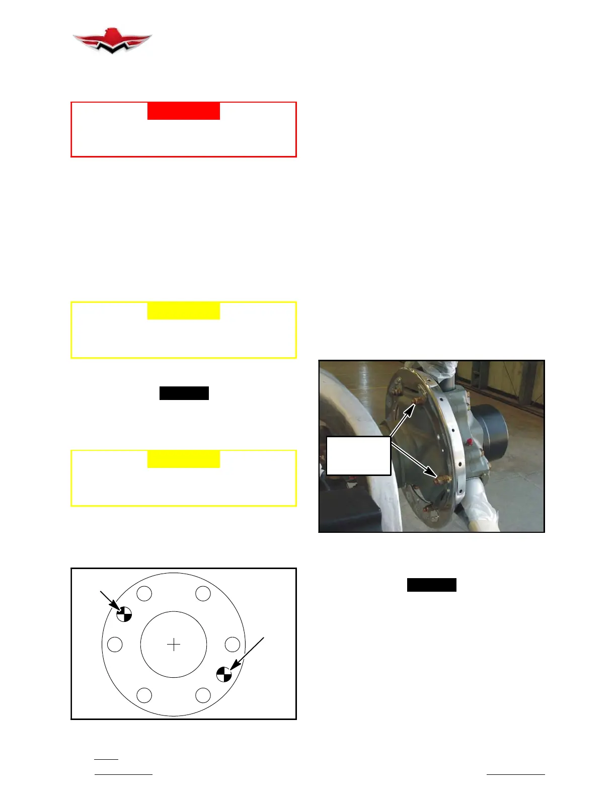
The propeller flange has six 1/2 inch studs configured in
a four inch circle (Figure 61- 2). Two dowel pins are also
provided to transfer torque and index the propeller with
respect to the engine crankshaft. The dowel pin loca-
tions used on a particular propeller installation are indi-
cated in the propeller model stamped on the hub. The
engine TC mark is aligned with one dowel- pin hole and
will be pointing up and aligned with the engine spit line
when cylinder #6 is at TDC.
The spinner support must be mounted before the pro-
peller can be installed.
SPINNER BULKHEAD TO PROPELLER HUB
INSTALLATION
1. Remove the nuts from the hub clamping bolts (Fig-
ure 61- 3) that are located on either side of the blade
shank. The remaining nuts/bolts should not be dis-
turbed. Do not remove the bolts.
2. Place the spinner bulkhead spacers on the hub
clamping bolts. Install the spinner bulkhead over the
installed spacers on the hub clamping bolts.
HUB
CLAMPING
BOLTS
HARTZELL HUB CLAMPING BOLTS
FIGURE 61- 3
-NOTE-
When installing the spinner bulkhead on propel-
ler, place one “thin” washer and two “thick”
washers between spinner bulkhead and propeller
hub (Fig. 61- 1) and one “thick” washer under nut
on each hub clamping bolt (6 places) used to
mount spinner bulkhead. Refer to Hartzell Own-
er’s Manual Number 115N for nut torque.
3. Install at least one flat washer and a new self- lock-
ing nut on each of the hub clamping bolts used to mount
the spinner bulkhead. Torque the nuts per Torque Table
61- 4.
61-00-20
 Loading...


