MOONEY INTERNATIONAL CORPORATION
M20V SERVICE AND MAINTENANCE MANUAL
Date
MAR 2017
Rev Date
Page
7
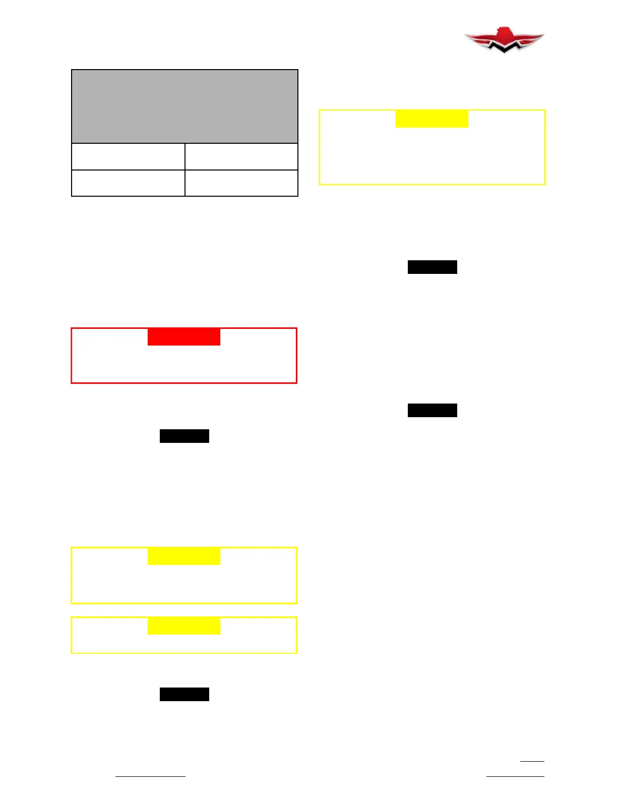
CAUTION
Mounting hardware must be clean and dry to
prevent excessive preload of the mounting
flange.
CAUTION
All torques listed are dry torque.
Hub clamping bolts/spin-
ner mtg. nuts
20- 22 ft- lbs
(27.1- 29.8 Nm)
Flange propeller mtg.
nuts
70- 80 ft- lbs
(95- 108 Nm)
TORQUE TABLE
FIGURE 61- 4
PROPELLER INSTALLATION
1. Perform the appropriate steps provided in Spinner
Bulkhead to Propeller Hub installation.
2. Clean the engine flange and propeller flange with
Quick Dry Stoddard Solvent or MEK.
3. Install the O- ring in the O- ring groove in the hub
bore
-WARNING-
Make sure the sling is rated up to 800 Lbs.
(363 KG) to support the weight of the propeller
assembly during installation.
4. With a suitable crane hoist and sling, carefully
move the propeller assembly to the aircraft engine
mounting flange in preparation for installation.
-NOTE-
If the propeller is equipped with an anti- ice or a
de- ice system, follow the applicable manufactur-
er’s instructions for installation of the anti- ice or
de- ice system hardware.
5. Install the propeller on the engine flange. Make
certain to align the dowel pins in the propeller flange
with the corresponding holes in the engine mounting
flange.
-CAUTION-
Mounting hardware must be clean and dry to
prevent excessive preload of the mounting
flange.
-CAUTION-
Tighten nuts evenly to avoid hub damage.
6. Torque the 1/2 inch propeller mounting lock nuts
(dry) as indicated in Torque Table (Figure 61- 4).
-NOTE-
Safety wire is not required (by Hartzell) in the
mounting studs
7. Install the propeller spinner dome in accordance
with Spinner Installation.
SPINNER INSTALLATION
-CAUTION-
To prevent damage to the blade and blade
paint, wrap the blade shanks in several layers
of masking or duct tape before installing the
spinner dome. Remove tape after the spinner
is installed.
1. Examine the interior of the spinner dome. The
spinner dome has an internal support (Figure 61- 1)
that encircles the propeller cylinder. The cylinder may
need to be wrapped with one or more layers of abrasion
and wear resistant UHMW tape (Hartzell P/N
B- 6654- 100).
-NOTE-
The UHMW tape on the cylinder should be
checked for smoothness of tape layers and that
spinner dome internal support fits snug against
cylinder. Spinner dome internal support must fit
snugly on cylinder, or cylinder will become dam-
aged by chafing.
2. Install the spinner and check for a snug fit where
the internal support contacts the cylinder. If the support
does not fit snugly on the cylinder, apply a layer of tape
and recheck. Repeat until the spinner support fits snug-
ly on the cylinder.
-NOTE-
When the spinner dome has been removed to
facilitate maintenance, check the spinner internal
support to cylinder fit. If the spinner loosens in
service, add one or more layers of UHMW tape to
the cylinder until the spinner fits snugly.
3. Secure the spinner to the spinner bulkhead or
adapter ring with the supplied screws and washers. To
avoid damaging the aircraft cowling, screws must not
extend more than three threads past the bulkhead nut-
plates.
61-10-00 - PROPELLER ASSEMBLY
Preflight inspection should be accomplished prior to
each flight to determine: if blades have been damaged,
if any abnormal looseness is evident between hub and
blades or if there is any evidence of oil leakage. Propel-
ler must be repaired if any of above is evident.
The propeller is to be lubricated at intervals not to ex-
ceed 100 hours or at 12 calendar months, whichever
occurs first.
If annual operation is significantly less than 100 hours,
calendar lubrication intervals should be reduced to six
months.
If the aircraft is operated or stored under adverse atmo-
spheric conditions, e.g., high humidity, salt air, calendar
lubrication intervals should be reduced to six months.
Owners of high use aircraft may extend their lubrication
interval. Lubrication interval may be gradually ex-
61-10-00
 Loading...


