MOONEY INTERNATIONAL CORPORATION
M20V SERVICE AND MAINTENANCE MANUAL
Page
Date
21
MAR 2017
Rev Date
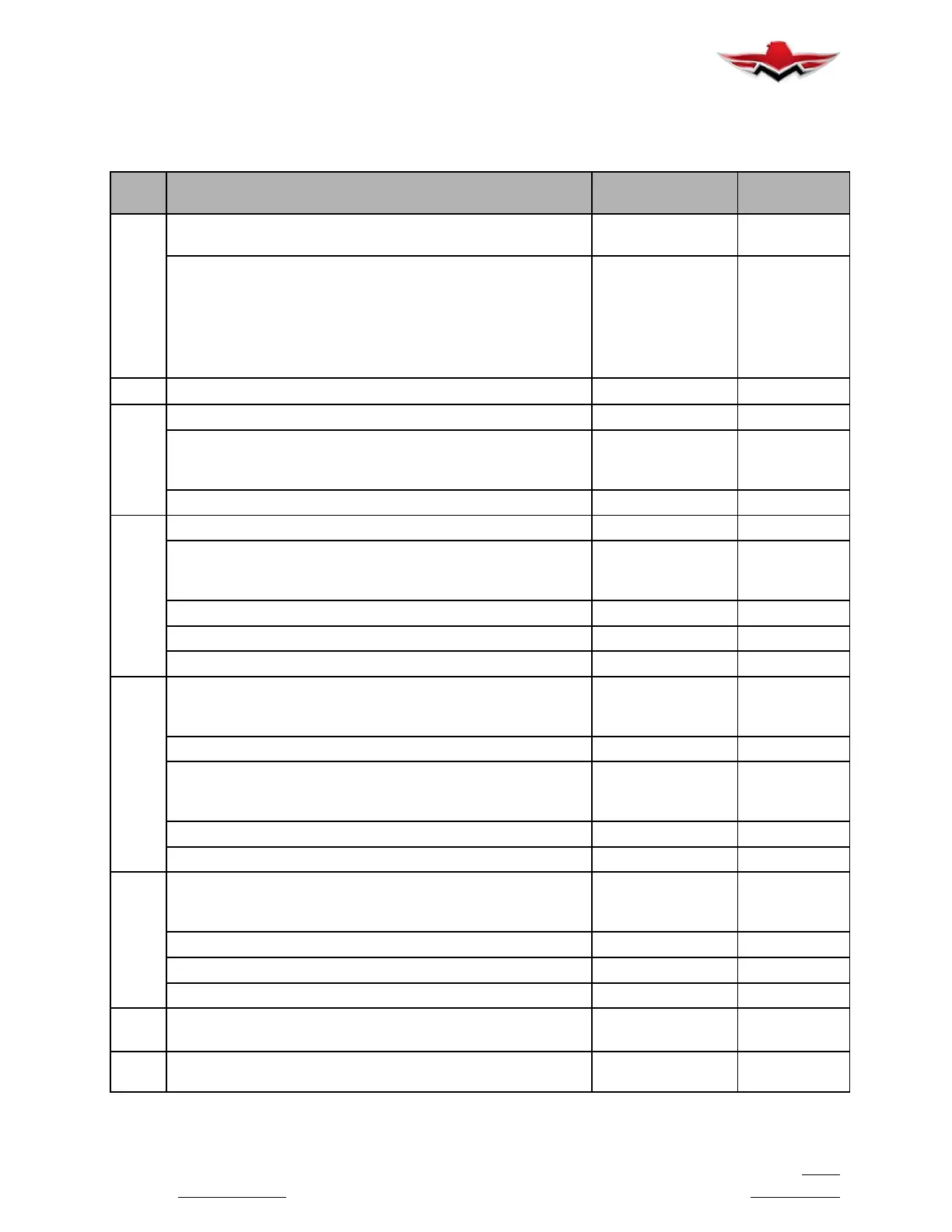
REFERENCE FIGURE 5- 1 FOR LOCATION OF THE FOLLOWING COMPONENTS
NOTE - Access covers riveted in place during production need not be removed for routine inspections.
5-20-09 - ACCESS COVER IDENTIFICATION, LUBRICATION AND SERVICE GUIDE
ITEM
NO.
ITEM DESCRIPTION LUBRICATION
SYMBOL *
INTERVAL
(HOURS)
1 Flight Instruments
Turn Coordinator
- **
Control System Adjustments:
Control Column Bearing Ball
Control Column Bearing Ball (P/N 710070- 501)
Rod End Bearings
Universal Joints
Bellcranks
DRY
100
N/A
100
100
100
2 Engine Cowling
û
100
3 Nose Gear Grease Fittings
100
Retraction Tube Rod End Bearings
Bellcranks
Bungees
100
100
100
Gear Door Rod End Bearings
50
4 Main Gear Grease Fittings
100
Retraction Tube Rod End Bearings
Bellcranks
Bungees
100
100
100
Gear Door Rod End Bearings
50
Electric Gear Actuator Gear Box ***
AR
Electric Gear Actuator Ball Screw
@
1000
5 Elevator & Rudder Controls:
Control Tube Rod End Bearings
Bellcranks
100
100
Batteries - -
Stabilizer Trim Control Shaft:
Universal Joints
Guide Blocks
#
100
100
Hydraulic Reservoir
50
Oxygen, High Pressure Fittings
ñ
50
6 Elevator & Rudder Controls:
Control Tube Rod End Bearings
Bellcranks
100
100
Stabilizer Trim Jack Screw/Actuator Brgs
100
Variable Downspring System
100
Tail Strobe Light Power Supply
û
100
7 Empennage Attach Points
Stabilizer Trim Attach Point
û
û
100
100
8 Elevator & Rudder Controls:
Control Tube Rod End Bearings
100
5-20-09
 Loading...


