MOONEY INTERNATIONAL C ORPORATION
M20V SERVICE AND MAINTENANCE MANUAL
Date
MAR 2017
Rev Date
Page
14
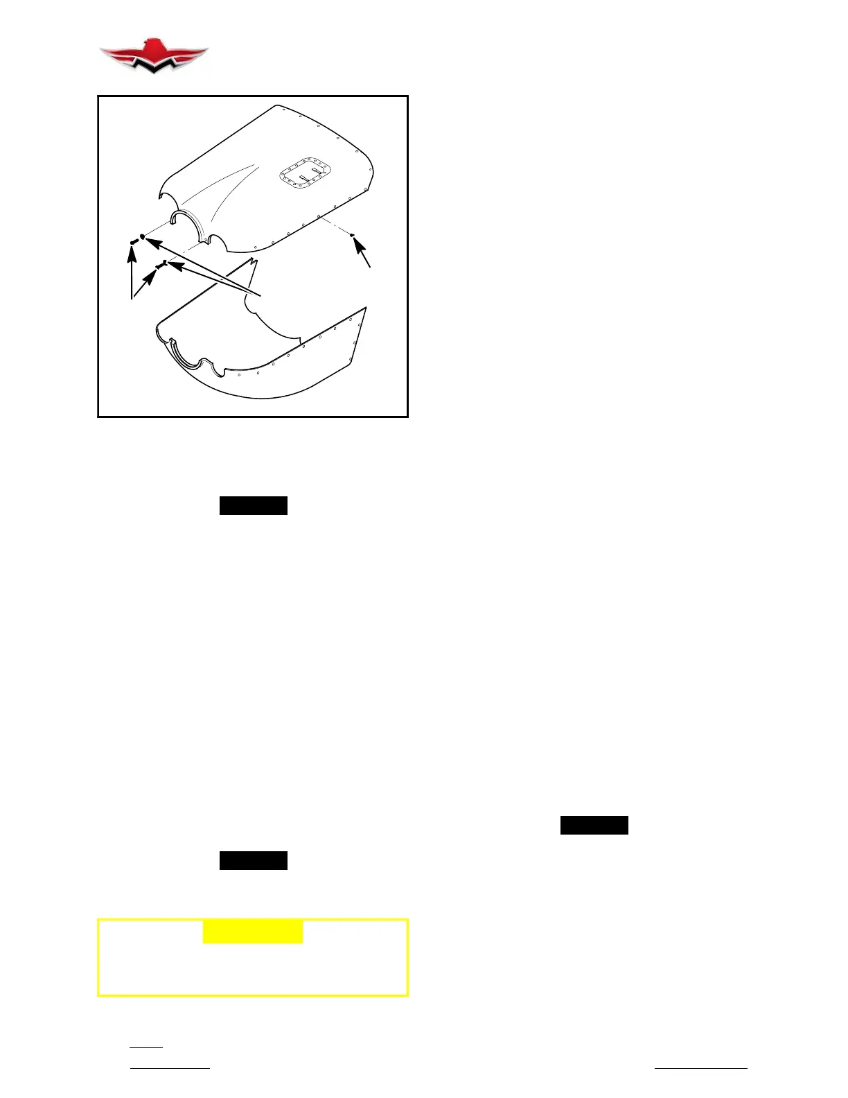
CAMLOCS
SCREWS
(TYP.)
WASHERS
COWLING MOUNTING HARDWARE
FIGURE 71- 4
71-11-00 - COWLING INSTALLATION
-NOTE-
Check condition of tape on firewall flange where
cowling will rest. Polyethylene tape, P/N
5421(UHMW) (3M), 1 in. wide is recommended.
This will decrease streaking during wet weather
operations. Also refer to Section 51-16-00 Carbon
Fiber Repair.
71-11-01 - BOTTOM COWLING
1. The bottom cowling is installed “first” in reverse se-
quence of removal.
71-11-02 - TOP COWLING
1. The top cowling is installed in reverse sequence of
removal.
71-12-00 - ENGINE COWL FLAPS
Not applicable to Mooney M20V aircraft.
71-20-00 - ENGINE MOUNTS
The M20V engine mount is a welded, bed type,
dyna- focal mount assembly constructed of 4130
chrome- moly steel tubing.
-NOTE-
All shock mounts should be replaced at engine
change.
-CAUTION-
The arrangement of engine isolator mounts
is extremely critical. Make certain they are
arranged as shown in Figure 71- 5.
Rubber shock mounts are installed in a specific se-
quence for proper dampening of engine and propeller
power pulses.
The sequence of assembly displayed in Figure 71- 5
must be observed.
71-20-01 - ENGINE MOUNT REPLACEMENT
1. ENGINE MOUNT REMOVAL.
A. Remove top and bottom cowling. Support the
engine using an “A” Frame with chain hoist or hydraulic
“Cherry Picker” and hook into the front and rear engine
lifting hooks. Remove or disconnect any components
that prevent lifting engine slightly to remove engine
isolator mounts.
B. Remove all four (4) retaining bolts, washers,
heat shields and lower isolators at all four locations.
Keep heat shield and mounting hardware lift engine to
allow removal of all four upper engine isolator mounts
and hardware. Inspect Heli-Coils in engine legs for any
damage i.e., cross- threading. Replace legs as re-
quired.
2. ENGINE MOUNT INSTALLATION.
A. Use “dummy” bolts (NAS6607-15 or equivalent)
and washers to secure each of the upper halves of isol-
ator mounts. Ensure upper washer and heat shield are
installed between isolator and engine motor mount
castings (4 places). Tighten bolts to compress rubber
mounts to approximate thickness shown in Figure
71- 6.
B. Before lowering engine, lube all four mount cups
with silicone lubricant to help facilitate alignment.
Slowly lower engine into motor mount cradle. Support
weight of engine with lift until engine is properly placed
in mount. When engine is first lowered, the isolator
mounts will not rest squarely in the cups on the mount
refer to Figure 71- 6.
C. Seat both rear mounts first, then front left & right
mounts. Use a large flat screwdriver to pry mounts into
cups. This step requires a considerable amount of pa-
tience and “elbow grease” - refer to Figure 71- 6.
D. Once top engine mounts are all seated in the
cups, begin removing “dummy” bolts and washers.
Start at right rear (RR), then left rear (LR), left front (LF),
and right front (RF).
-NOTE-
Keep bolt and washer centered in the cup to pre-
vent binding and stripping of threads.
E. Correctly position each heat shield in place per
Figure 71- 5, index drain holes at lowest point of install-
ation & index cutouts parallel to sides of engine mount.
Make sure heat shields are oriented to prevent chaff-
ing or interference on engine mount or engine compon-
ents and drain holes at lowest part of installation. Install
both retaining bolts, washers and torque to specifica-
tion shown in Figure 71- 5.
71-11-00
 Loading...


