MOONEY INTERNATIONAL CORPORATION
M20V SERVICE AND MAINTENANCE MANUAL
Page
Date
6
MAR 2017
Rev Date
UPPER
1
2
3
4
5
6
1
2
3
4
5
6
1
2
3
4
5
6
1
5
3
2
4
6
SPARK PLUGS
RIGHT MAG
LEFT MAG
UPPER
SPARK PLUGS
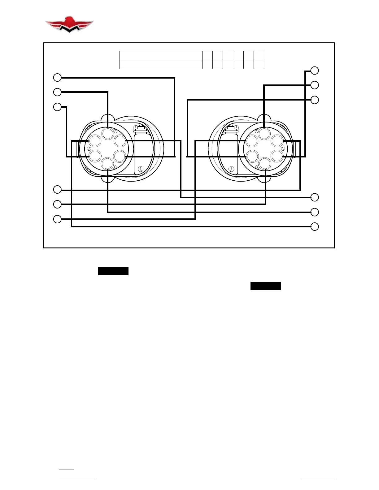
ENGINE FIRING ORDER
MAGNETO FIRING ORDER
1 63254
1 23456
IGNITION WIRING DIAGRAM
FIGURE 74- 1
-NOTE-
Aircraft which are flown at higher altitudes during
normal flight operations require more frequent
maintenance on ignition components than air-
craft flown at lower altitudes.
74-20-00 - ENGINE FIRING ORDER
Engine firing order is 1- 6- 3- 2- 5- 4 (Figure 74- 1). Ob-
serve position of No. 1 cable terminal in magneto outlet
plate in relation to magneto case. As viewed from dis-
tributor end, magneto rotor turns counter- clockwise,
passing in succession, terminals of spark plug cables
in engine firing order. Cables are connected to magne-
tos so right magneto fires upper plugs on right side and
lower plugs on left side. The left magneto fires upper
plugs on left side and lower plugs on right side. The
magneto cases, spark plugs, cables and connections
are shielded to prevent radio interference.
-NOTE-
It is recommended that all spark plugs be re-
moved, inspected, cleaned, re- gapped and rein-
stalled in the same cylinder but in a different
spark plug hole every 100 hrs. Replace spark
plugs after 400 Hrs. of operation.
74-30-00 - SWITCHING
The Magneto/Starter Switch is co nnected to magneto
grounding wires (“P” leads) of both magnetos. Turning
this switch from “BOTH” to “OFF” or from “R” to “L” to
“OFF” will ground out both or either magneto. (See
Section 74-00-00 for grounding sequence.)
74- 20- 00
 Loading...


