19
Rev. 1.0
11/08/2017
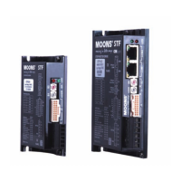
STF-R/C Hardware Manual
400-820-9661
3.2 Digital Outputs
3.2.1 Y1, Y2, Y3 Digital Outputs
Y1 can be used as alarm output, motion status output or general purpose output.
Y2 can be used as brake output, motion status output or general purpose output.
Y3 cab be used as tach-out, timing signal output(50pulse/rev), motion status output or general
purpose output.
Please use STF Congurator software for Y1,Y2 and Y3 function conguration.
Following graphs shows some common connection methods for the outputs:
NOTE: Do not connect the outputs to more than 30VDC power supply. And the current of
each output terminal must not exceed 100mA.
Connecting a sinking output
Connecting a sinking output with PLC’s input
Connecting a sourcing output with PLC’s input
Driving a relay
STF
Drive
5-24 VDC
Power Supply
+ –
Load
Y1/2/3-
Y1/2/3+
CLP
CDV 42-5
ylppuS rewoP
+ –
Y1/2/3-
Y1/2/3+
IN
COM
STF
Drive
PLC
5-24 VDC
Power Supply
+
–
Y1/2/3-
Y1/2/3+
COM
IN
STF
Drive
STF
Drive
1N4935 suppression diode
5-24 VDC
Power Supply
+ –
relay
Y1/2/3-
Y1/2/3+