Do you have a question about the Moons' Lin Engineering R701P and is the answer not in the manual?
Provides telephone and email addresses for technical support assistance.
Lists essential components and setup steps before operating the driver.
Covers warning symbols, reliability disclaimers, and liability.
Explains how inputs are driven by various voltage sources.
Details wiring for optocoupler inputs using +5V and common ground.
Lists electrical parameters like supply voltage, peak current, and resolution.
Outlines operational parameters like pulse timing, temperature, and humidity limits.
Provides physical dimensions, weight, and mounting information.
Advises on heatsink use for current settings above 3 Amps.
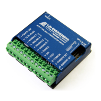
Details the function and description for each pin on the driver.
Lists necessary components for connecting the R701P driver.
Highlights critical warnings regarding power supply voltage and motor disconnection.
Details connecting power ground and voltage supply.
Explains connecting motor windings to terminals.
Details connections for disable, direction, and step inputs.
Provides a table of resistor values for setting motor current.
Lists resistor values for the opto supply to maintain isolation.
Guides on adjusting the trimpot for smooth low-speed operation.
Explains the feature that reduces current when the motor is holding.
Details configuration options for larger frame size motors.
Details dip switch settings for current, auto standby, and motor type.
Describes the two-piece modular main connector.
Illustrates connecting a 4-lead wire motor.
Shows how to connect a 6-lead wire motor in half winding.
Illustrates connecting a 6-lead wire motor in full winding.
Shows connecting an 8-lead wire motor in parallel.
Details connecting an 8-lead wire motor in series.
Troubleshoots why the motor is in holding position but not rotating.
Provides guidance on selecting resistors when a specific value is unavailable.
| Brand | Moons' |
|---|---|
| Model | Lin Engineering R701P |
| Category | Control Unit |
| Language | English |