LIN ENGINEERING Page 9 Version 6.70
R701P User Manual 02/15/2022
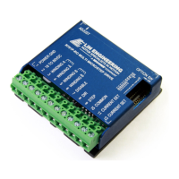
Figure 3: Connections Diagram
Resistor Values for the Opto Supply
The optocouplers must be powered by an external power supply to maintain isolation. The Opto
Supply (Terminal 10) for the optocouplers can be between +5 to 24 VDC with respect to the signal
input. It is recommended to use a +5 VDC Opto Supply in order to limit the current going into the
optocouplers to 16 mA. However, if the supply is greater than +5 VDC then a resistor must be
connected in series with the STEP line and another one in series with the DIRECTION line to maintain
16 mA of current running through the optocouplers. Refer to Table 4 for the corresponding Resistor
Values.
The Resistor shall be put in series with the Positive Terminal of the Opto Supply and with Terminal 8
(Direction) and Terminal 9 (Step).
Opto Supply
Resistor Value
(Ohms 5%)
5 V -
10 V 330 Ohm, 1/8 Watt
15 V 680 Ohm, 1/4 Watt
20 V 1.0K Ohm, 1/4 Watt
24 V 1.2K Ohm, 1/2 Watt
Table 4: Opto Supply Resistor Values