LIN ENGINEERING Page 6 Version 6.70
R701P User Manual 02/15/2022
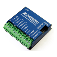
5. PIN ASSIGNMENTS
PIN # FUNCTION DESCRIPTION
1 Power Ground
power supply connects
2 +V
Motor Supply Voltage. +18 to +80
VDC
3 Phase A
4 Phase A-
- of the stepping motor
5 Phase B
6 Phase B-
- of the stepping motor
7
Enable/Disable
Input
ground to the logic functions (i.e. step
8 Direction Input
This input is used to change the rotation
direction of the motor
9 Step Clock
Negative (falling) going edge on this input
advances the motor one
increment. The size of
the increment is depending on the image set.
10 Opto Supply
+5 VDC input used to supply power to the
isolated logic inputs. A
resistor must be used if
the supply is greater than 5 VDC.
11 Current Set
-collector drive.
12 Current Set
-collector drive.
Table 1: Pin Assignments
6. CONNECTION SPECIFICATIONS
List of Parts
Connection of the R701 is simple. Here is what you need:
• External Main Power Supply (+18 to +80 VDC)
• +5 VDC Power Supply used as the Opto Supply (See Table 2)
• A Function Generator
• An appropriate Bipolar Stepper Motor
WARNING! Power supply voltage in excess of +80 VDC will damage the R701P. Do not
short the motor leads to each other or to ground. This will also damage the board.
WARNING! Do not shut off the power while the motor is moving, this could result in a
catastrophic failure of the drive.