LIN ENGINEERING Page 4 Version 6.70
R701P User Manual 02/15/2022
1. FEATURES
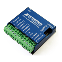
R701P
• 10 microstepping driver
• Common Ground or Common + 5 Volts Input Option Available
• Optically isolated Step, Direction, and Disable/Enable inputs
• Automatic Current Reduction
• Adjustable trimpot for noise and vibration reduction
• Operates from 18 to 80 VDC
• Selectable Driver Peak Current Ranges: 0 to 7 Amps
• Low Power Dissipation from 1 to 12 Watts (1 to 7 Amps)
• Excellent sinusoidal current waveform for smooth operation
• Low current ripple for low noise
• Low Cost
• High Efficiency
Input Option Header
The R701P has no internal jumpers for input options. The inputs can be driven by a source where
+5V, + 3.3V or ground is only available.
Using +5V, Common Ground, and Disable for Optos
Your negative 5V supply will connect to the “+5 VDC” line, Pin 10. The negative side of your step
pulses should then connect to your “Step” line, Pin 9. The positive side of your +5V and the positive
side of your step pulses should be tied together.
To disable the drive, connect the disable pin to Pin 12, the end of the current set resistor pin. To
change direction of rotation, connect the direction pin to the +5V and + step pulse connection.
2. ELECTRICAL SPECIFICATIONS
R701P
Supply Voltage: +18 to 80 VDC
Peak Current: 0 to 7 Amps
Auto Current Reduction: 70% of set current, 1 second after last Step Pulse
Quiescent Current: 15 mAmps or less
Resolution: 10 microstepping
Motor Inductance: 1-50 mH
3. OPERATING SPECIFICATIONS
Step Pulse Time on falling edge (0) (COMMON 3.3V-5V): 0.5 μS minimum
Step Pulse Time on rising edge (1) (COMMON 3.3V-5V): 3.0 μS minimum
Step Pulse Time on falling edge (0) (GND): 3 μS minimum
Step Pulse Time on rising edge (1) (GND): 0.5 μS minimum
Direction Setup: 0 μS minimum
Operating Temperature: 0° to 70° Celsius
Humidity Range: 0 to 95% (non-condensing)
Power Dissipation: 1 to 13 Watts (1 to 7 Amps)