LIN ENGINEERING Page 8 Version 6.70
R701P User Manual 02/15/2022
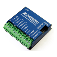
These inputs are optically isolated from the rest of the drive. Terminal 10 is the common anode
connection for the opto-isolators and must be connected to the +3.3VDC,+5 VDC supply of your
indexer or pulse generator.
These inputs are meant to be driven by 3.3V to 5.5V logic capable of sourcing or sinking 2.5 mA of
current. The minimum logic “0” time is .5 usec while the minimum logic “1” time is 4 usec.
Microstepping occurs on the falling edge of the step input.
Terminal 11: Current Set (OPTIONAL) - Connect one end of the resistor to this terminal.
Terminal 12: Current Set (OPTIONAL) - Connect the other end of the resistor to this terminal.
This terminal is a filter ground.
Resistor Values to set the Current
DIP switches 1, 2, 3 ,4, and 5 must be set to ON if an external current set resistor is used.
Please use the corresponding resistor for the correct current setting for your motor.
If you are using the driver with currents of 1 to 7 Amps, R = 47*I/(7-I).
(R = Resistor in kΩ)
(Ohms 5%)