LIN ENGINEERING Page 7 Version 6.70
R701P User Manual 02/15/2022
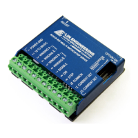
How to Connect
For safety reasons, please connect the power supply (Terminal 2) last.
Terminal 1: Power Ground - Connect the power supply ground here.
Terminal 2: +18 to 80 VDC - Connect the positive (+) end of the power supply here.
The maximum power supply current required is 67% of the motor’s rated phase current. An
unregulated power supply may be used as long as the voltage stays between the limits; keep the
ripple voltage to 10% or less for best results. The drive has a 2 second power-on reset time before
the motor is energized.
Optional:
If the power supply is more than 1 foot (300 mm) away from the driver, a 470 μF capacitor can be
connected across the R701P power supply terminals. Keep the capacitor lead length to 1 inch (25
mm) or less. Note: If using multiple drives daisy chained on a single power supply you will need a
capacitor for each drive.
The choice of power supply voltage depends on the high speed performance required of the motor.
Doubling the voltage doubles the motor’s high speed power. In all cases the power supply voltage
should be no less than 4 times or no more than 25 times the motor’s rated voltage. The motor may
not run as smoothly as possible if it is too low, and the board may be damaged if it is run too high.
Terminal 3: Phase A Terminal 4: Phase A
Terminal 5: Phase B Terminal 6: Phase B
Connect one motor winding to terminals 3 & 4. Connect the other winding to terminals 5 & 6. Turn
the power supply off when connecting or disconnecting the motor. If the motor turns in the wrong
direction, reverse the motor windings for terminal 3 & 4. Please see the “8. Motor Connections”
section for connecting 4, 6, or 8 wire motors.
Terminal 7: Disable – Short this pin to filter ground (pin 12, end of current set resistor slot) to disable
the unit. Shorting it to this ground forces winding currents to zero and stops all output switching
activity. The R701P will continue totalizing step and direction inputs if any are sent. The power
supply current drops to less than 15mAmps. The motor will return to its original position when the
disable input is released if no step pulses have been sent and the motor has not been moved more
than 20 microsteps (2 full steps).
Terminal 8: Direction Input - Closing this connection to signal ground will change the direction of the
rotating motor
Terminal 9: Step Input - Connect the positive (+) terminal of the function generator to this terminal. If
you have an alternative pulse generator, connect it to this terminal.
Terminal 10: +3.3VDC, +5VDC, GND - Connect the +3.3VDC, +5VDC, or GND