RIY
4
The Interface Solution Experts
USED TO SAVE
CALIBRATION VALUES
USED TO SET OR
TRIM FULL SCALE
USED TO DISREGARD LAST
ENTRY AND RETURN TO
OPERATE MODE
USED TO SET
OR TRIM ZERO
SAVE
CANCEL
ZERO SPAN
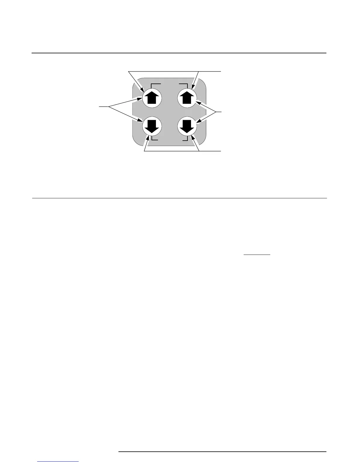
Figure 1. RIY Front Panel Push Buttons
The Up arrows:
• display the latest calibrated setting for zero or
span, respectively, when pressed individually
during normal operation (units with LCD’s
only); does not affect the output of the RIY
• increment zero or span values, respectively,
when pressed individually while in
quick
ranging
(units with LCD’s only)
• increment the ‘trim’ value for the zero- and 100-
percent output levels in
standard ranging
• save the calibration setting for zero or span
while in the calibrate mode, then returns the
unit to normal operation, when both are
pressed simultaneously
The Down arrows:
• display the latest calibrated setting for zero or
span, respectively, when pressed individually
during normal operation (units with LCD’s
only); does not affect the output of the RIY
• decrement zero or span values, respectively,
when pressed individually while in
quick
ranging
(units with LCD’s only)
• decrement the ‘trim’ value for the zero- and
100-percent output levels in
standard ranging
• cancel the calibration mode and returns the unit
to normal operation when both are pressed
simultaneously; retains previous values
Pressing the ZERO or SPAN Up and Down arrows
simultaneously sets the unit to the calibrate mode (if
enabled through switch settings) for that particular
setting.
CAUTION
The push buttons are not designed to be
actuated with sharp, pointed objects.
Using a pen, screwdriver, or other sharp
object will damage the push buttons.
Using the Configuration Switches
A rotary switch and a single in-line package (SIP)
switch are used to configure the RIY for user-se-
lectable operating and calibration parameters.
Figure 2 shows the layout of the configuration
switches and the switch setting options for SW301.
The switch settings for rotary switch SW302 are listed
in table 2. The reference designators and physical
layout of the switches in the HP- and DIN-style units
are identical.
The switches for HP-style units are accessed through
a cutout at the rear of the unit. The cutout is filled
with a small, removable panel. A narrow, slotted-
head screwdriver may be used to gently pry the panel
off the unit to access the switches.
 Loading...