RIY
The Interface Solution Experts
5
-6
-5
-4
-3
-2
-1
ON OFF
1
2
3
6
7
9
5
0
A
B
D
E
F
4
8
C
SW 302
SW 301
ON
OFF
-2 OFF/-3 OFF
-2 OFF/-3 ON
-2 ON/-3 ANY
ON
OFF
ON
OFF
ON
OFF
DISPLAYS CELSIUS
DISPLAYS FAHRENHEIT
2-WIRE, DUAL 2-WIRE
3-WIRE, DUAL 3-WIRE
4-W IRE, TRIPLE 2-W IRE
DOWNSCALE DRIVE
UPSCALE DRIVE
QUICK RANGING
STANDARD RANGING
KEYBOARD LOCKOUT
KEYBOARD ENABLE
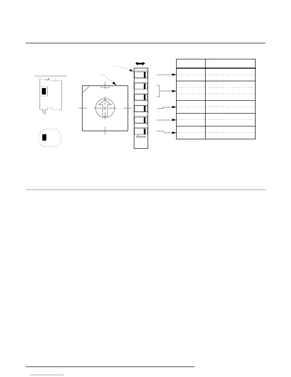
SETTINGS FEATURES
ORIENTATION
HP
DIN
NOTES: 1. Refer to table 2 for SW 302 switch setting uses.
2. The relative position of SW 301 and SW 302 is identical for HP- and DIN-style units.
3. SW301-6 may be inactive in earlier units. In these units, the switch setting can be disregar ded.
Figure 2. Internal Switches, Layout, Designations, and Settings
Switches for DIN-style units are accessed by remov-
ing a small, L-shaped panel from the upper right-side
of the unit. This panel is bent over the top, right-side
edge of the unit and is secured with a single screw on
top. A Phillips-head screwdriver is required to
remove one screw securing the small L-shaped panel
to the housing frame.
The configuration switches are used to set the
following features:
SW301-1 — Displayed Temperature Type
ON
–
Sensor input displayed in Celsius
OFF – Sensor input displayed in Fahrenheit
This switch determines the type of temperature
units that will be displayed on the LCD. If an
ohms range is selected, the display will show
OHMS and this switch is ignored.
SW301-2 & -3 — Number of Wires or Sensors
These two switches determine the number of
wires for a single sensor input, or the number of
sensors of a multi-sensor input configuration.
Refer to table 2.
SW301-4 — Upscale/Downscale on Fault
ON – Downscale Output Drive on Fault
OFF – Upscale Output Drive on Fault
This switch determines the reaction of the RIY
output when an error is detected (during power-
on diagnostics) or when an input or sensor lead is
physically open.
SW301-5 — Ranging Method
ON
–
Quick Ranging (for units with LCD’s only)
OFF – Standard Ranging
Quick Ranging
can only be performed on units
with an LCD. To set the 4-20 mA output with this
ranging method, dc power is the only input
needed for the unit. The pushbuttons are used to
set the zero and full-scale inputs.
Standard Ranging
requires an input source, an
output monitoring device, and dc power. The
push buttons are used to capture the zero and
full-scale input values and to trim the zero- and
100-percent output settings.
 Loading...