Do you have a question about the MORLEY-IAS ZX1Se and is the answer not in the manual?
Manual covers usage and operation, manufacturer reserves right to modify.
Procedures to avoid injury and equipment damage, requires trained user.
Equipment must comply with national/local regulations.
Describes three user control levels: Level 1 (inhibited keys), Level 2 (operations), Level 3 (installer).
Up to ten Level 2 passwords, assigned/changed at Level 3.
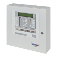
Panel has two key groups: 5 system control keys and 17 interactive/alphanumeric keys.
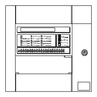
LEDs show panel status (fire, fault, test, etc.) and zone status.
Details indicator color, function, and action required for each LED.
LCD displays status, date/time, or scrolls fire/fault conditions.
Display shows date, time, and 'All devices are within working limits'.
Shows examples of alphanumeric display during fire alarm events.
Shows examples of alphanumeric display during fault conditions.
Green AC Power LED, display shows time, date, and status messages.
AC Power LED flashes, buzzer sounds, display shows 'AC Fail' message.
FIRE LED illuminates, ZONE FIRE LEDs flash, buzzer sounds for fire alarms.
Manual call point can override programmed delays to activate outputs.
FAULT LED illuminates, display shows fault details, panel buzzer sounds.
Indicates AC Mains failure, battery low, or charger failure.
FAULT LED and other LEDs illuminate, display shows fault details.
FIRE LED illuminates, ZONE FIRE LEDs flash, buzzer sounds, display shows fire location.
Panel shows 'Battery Missing' or 'Battery Low/Charger Fail' messages.
FAULT LED and other LEDs illuminate, display shows fault details.
Actions for faults: acknowledge, reset, disablement of points/zones.
Indicates fire alarm via FIRE LED, ZONE FIRE LEDs, buzzer, and display.
Actions for fire alarms: mute buzzer, silence sounders, system reset.
Allows user to test system parts: LEDs, LCD, Zones, Outputs, Audible Indicator.
Allows setting of date and time on the alphanumeric display.
Allows enabling or disabling of zones, inputs, keys, delays, and day mode.
Selects print menu for devices, events, mode, setup, or disabled items.
Allows viewing of devices, log, faults, disablements, and system events.
Initial alarm warning with delay, requires acknowledgement to start Stage 2.
Second stage of delayed alarm, allows investigation before full alarm.
Functions for service engineers/installers, not covered in this manual.
Section for site name, address, contact, and installation details.
Table format for recording system events, actions, and completion.
| Number of Zones | 1 |
|---|---|
| Power Supply | 230V AC 50/60Hz |
| Communication Protocol | Apollo/Discovery, Hochiki ESP |
| Enclosure | Metal |
| Zones | 1 |
| Sounder circuits | 1 |
| Operating Temperature | -5°C to +40°C |
| Enclosure Rating | IP30 |
| Type | Control Panel |
| Input Voltage | 230V AC |