Rev. 00 of 01.01.2009 17 / 29
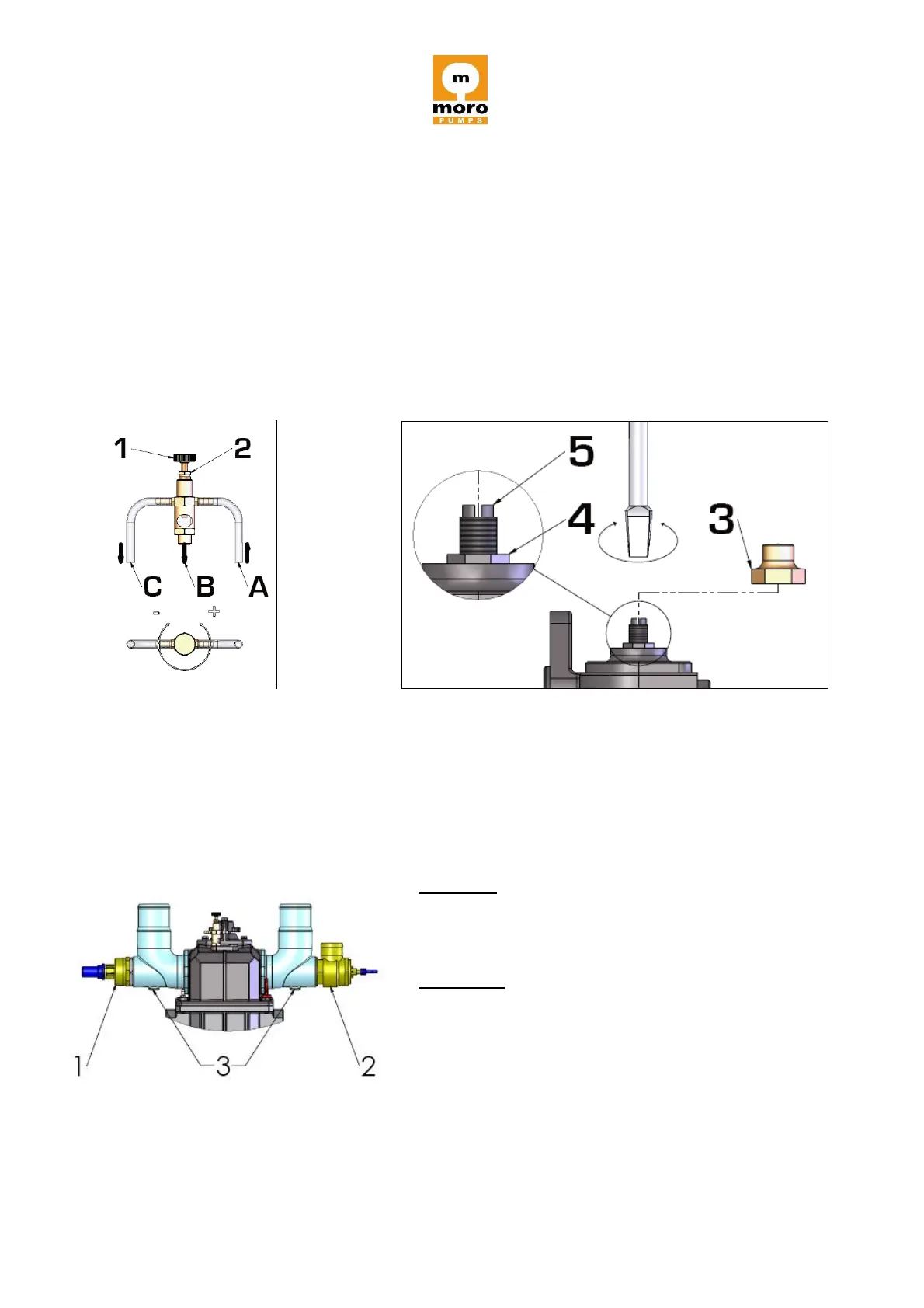
The oil from the tank reaches tube “A”, enters the vacuum pump through the passage “B”;
excess oil returns to the tank through tube “C”.
Standard regulation of oil delivery, in automatic lubrication, is carried out at our plant during the
final test of the vacuum pump. If, for any reason, a different flow rate is necessary (see Figure
7) proceed as follows:
remove cover “3”
loosen counternut “4”
operate the register pin “5”.
Rotating clockwise a reduced oil delivery is achieved (-); rotating anticlockwise an increased oil
delivery is achieved (+). When the regulation is over, tighten the counternut “4” and tighten the
cover “3”.
(figure 6) (figure 7)
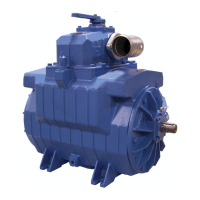
7. OVERPRESSURE AND VACUUM REGULATION VALVES
The vacuum pumps AIR series do not come with pressure and vacuum relief valves. These
accessories can be ordered separately, together with the aluminium hose connections or with
the cast iron manifold.
The threads on these accessories are Ø 2” NPT (pressure) and Ø 1 ½” NPT (vacuum).
Vacuum: excessive vacuum can cause damage to
the pump or vacuum tank. For this reason, we
recommend to use a vacuum regulation valve “1” set
to a max. value of 18” Hg.
Pressure: max. possible pressure is 43 absolute
p.s.i. (28 relative p.s.i.). We recommend using as
little positive pressure as possible. A 2” pressure
relief valve “2” should be used with a recommended
setting of 5 PSI.
To fit pressure/vacuum gauges, use the threaded
hole “3”, on the two aluminium hose kits which can
be provided on request.
No. 2 valve support hose kits in aluminium