Rev. 00 of 01.01.2009 18 / 29
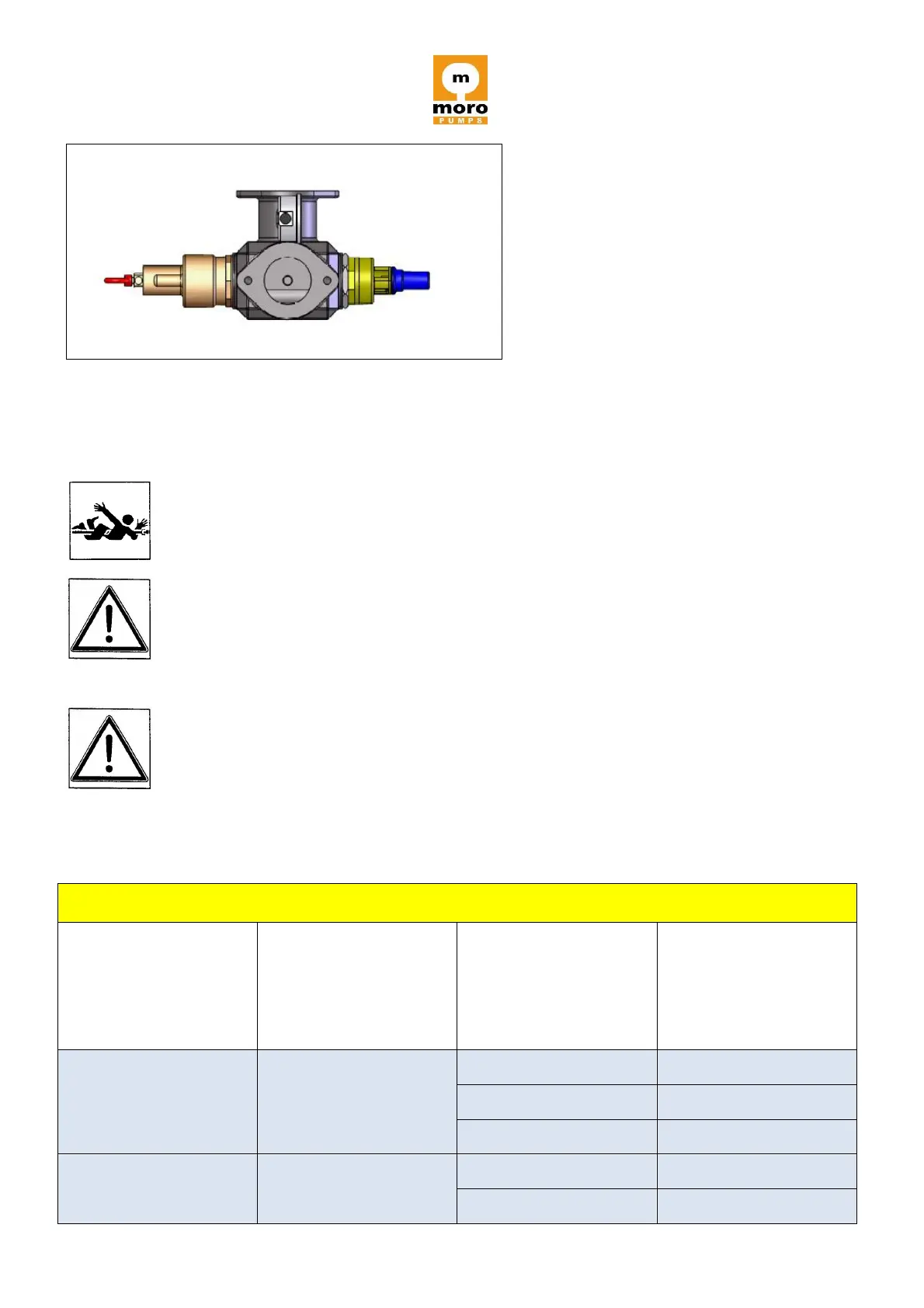
Cast iron manifold valve support kit
Vacuum and pressure relief valves should be set and locked as per manufacturer’s instructions.
Make sure suction and discharge hoses are connected prior to testing any
component of the vacuum system
.
In these conditions there is as well the risk to aspire foreign material from inside the
machine.
Current standards require that pressure relief valves be sized properly to insure all
necessary air can be discharged to achieve necessary regulated pressure. Use
table 4 below to determine the number of valves required to achieve proper
regulation.
Overpressure valves nominal flow rates according to I.S.P.E.S.L. E.1.D.2.
Inlet surface
Square inch
Reference pressure
Prelative (Pr) /
Pabsolute (Pa)
PSI