8
Morrison Bros. Co. ‑ Dubuque, IA ‑ 800‑553‑4840
1218C‑0142 PP rev 11‑28‑2018
Wiring
1. Install the Belden #7933A cable from the Channel Input Connector to be wired up through the conduit to the
1218 Sensor conduit junction box.
2. Connect the wiring to the Sensor rst. Trim excess cable and then strip 2 to 3 inches of sheathing to expose
the shield. Cut away the exposed foil shield, as well as the bare drain/shield wire. Use electrical tape or heat
shrink tubing to insulate the exposed end of the drain/shield wire.
3. Use 4 of the provided splice connectors (part number: 1018G-3136 2C) to connect each wire color pair
connector (see Table 1 for color code guidance). The wires must remain insulated to work properly. Do NOT
strip ends.
4. Insert the corresponding wire color pair all the way into the connector. Use pliers to squeeze the button to the
body on the connector. This will pierce the insulation and make the electrical connection. There is a jelly that
may squeeze out through the connector. This is to prevent corrosion of the connection, and will not harden.
5. After all 4 of the wire pairs are connected, fold the splices and wires into the junction box and replace the
junction box cover.
6. Return to the 1218C Electronic Tank Gauge Console. Trim excess cable 2 inches past the Channel Connector
and then strip the sheathing to expose the shield. Cut away the exposed foil shield, but do not cut the bare
drain/shield wire.
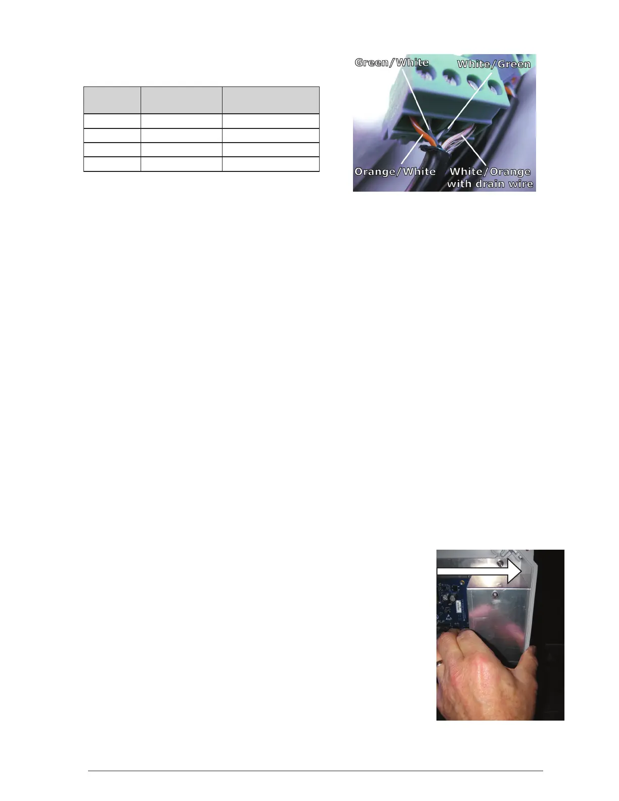
7. Strip 3/16 of an inch of insulation o each wire and twist the bare shield wire and the White/Orange wire
together.
8. Connect the wire colors to the indicated pin of the Channel Input connector (see Table 1 for color code
guidance). The connector may be removed for ease of installation.
9. If removed, reinstall the connector.
10. Secure the cable to the cable tie mount adjacent to the channel connector on the inside enclosure wall using
the supplied wire tie.
11. Repeat this process for each remaining Channels/Sensors.
Completion
1. Replace the cover previously removed and secure with the screws and at
washers; do not tighten the screws.
2. Slide the cover to the right snugly up against the enclosure wall as shown in
Figure 4.
3. Snug the screws in place.
Sensor
Wires (P4)
Wire Colors
1218C Connectors
V-Red Orange/White 1
C-Red Green/White 2
C- Black White/Green 3
V-Black White/Orange 4 with Drain wire
Channel Input Connector
Figure 4 Adjust the position
of the cover


 To Next Page