22
23
DK ENG
In situations where the stove is to be tted into a brick or non-combustible recess, we recom-
mend that the stove is installed with at least 10 cm clearance to the wall, this will allow room air
circulate around the stove; also the maintenance of the outside stove is easier. When applied to
masonry, a layer of wallpaper is normally classied as a non-combustible surface.
On the oor
National and Local Building Regulations must again be observed when considering the type,
thickness and area of the hearth to be used in the installation. The hearth temperature under
safety test was less than 65°C.
One should of course always make certain that the underlying oor surface can bear the
weight of the stove.
Clearances to furniture and soft furnishings
We recommend that the stove be installed 800 mm from furniture. Serious consideration
should also be given to positioning of any furniture that could be adversely aected by heat.
The clearances to combustible materials in front of the stove should be a minimum of 800
mm. When lit, a wood-burning stove gets hot and therefore adequate protection must be
provided, particularly in situations where there is a safety risk to children or the inrm. A
suitable safety guard around the stove should be considered.
The stoves handle also gets hot when the stove is lit, which is why a safety glove is included
with the stove.
1.5 The chimney
Only if National or Local Regulations permit are you permitted to connect a stove into a chim-
ney that is shared by another appliance. YOU MUST be aware of any applicable Regulations
in this respect.
The wood-burning stove must never be connected to a chimney to which a gas-burning stove
or appliance is connected.
An ecient modern stove places heavy demands on the chimney, and you should have the
chimney regularly swept and inspected by your approved chimney sweep.
The cross-sectional area of the chimney (at its narrowest point) must comply with National
and Local Building Regulations. Generally, the area needed for a Morsø wood-burning stove
installation should measure at least 175 cm2 (150 mm diameter).
An over-sized chimney is generally hard to keep warm and results in poor draft. In cases where
there is an oversized masonry chimney, it is recommended that the chimney be lined using an
appropriate chimney lining system with the correct internal diameter.
With respect to the chimney termination, all chimneys should terminate in accordance with
National and Local Building Regulations.
Note that National and Local Regulations also apply with regard to the placement of chim-
neys and ues in connection with thatched roofs. See the section on Draft Conditions, 1.9.
The chimney or ue system must be equipped with access doors for inspection and clean-
ing. The size of the cleaning door in the chimney must at least equal to that of the cross-
sectional area of the chimney. In the event that a chimney re occurs resulting from faulty
operation or prolonged use of damp wood fuel, close the air vents completely and contact
your local re department immediately.
1.6 Fluepipe connections
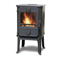
The stove comes standard with a smoke outlet (1) at the top and a cast-iron cover mounted
on the cast-iron back panel behind the convection back panels. If you want to install the stove
with the smoke exiting to the rear, knock the iron plates on the convection back panels out of
the small „bridges“ which hold the plates in place, using light, steady hammer taps. Remove
the smoke outlet from the stove, unbolt the cast-iron cover from the back panel and install it
in the top plate. Centre the smoke outlet in the hole on the back side of the stove and bolt it
securely in place with the bolts and clamps provided.
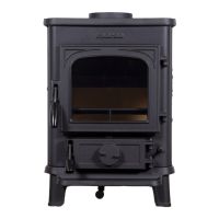
How to position the access bae
The smoke shield (2) helps ensure a highly e-
cient stove. The smoke shield is not tted during
production; it has been packed for transit inside
the ash can of the stove.
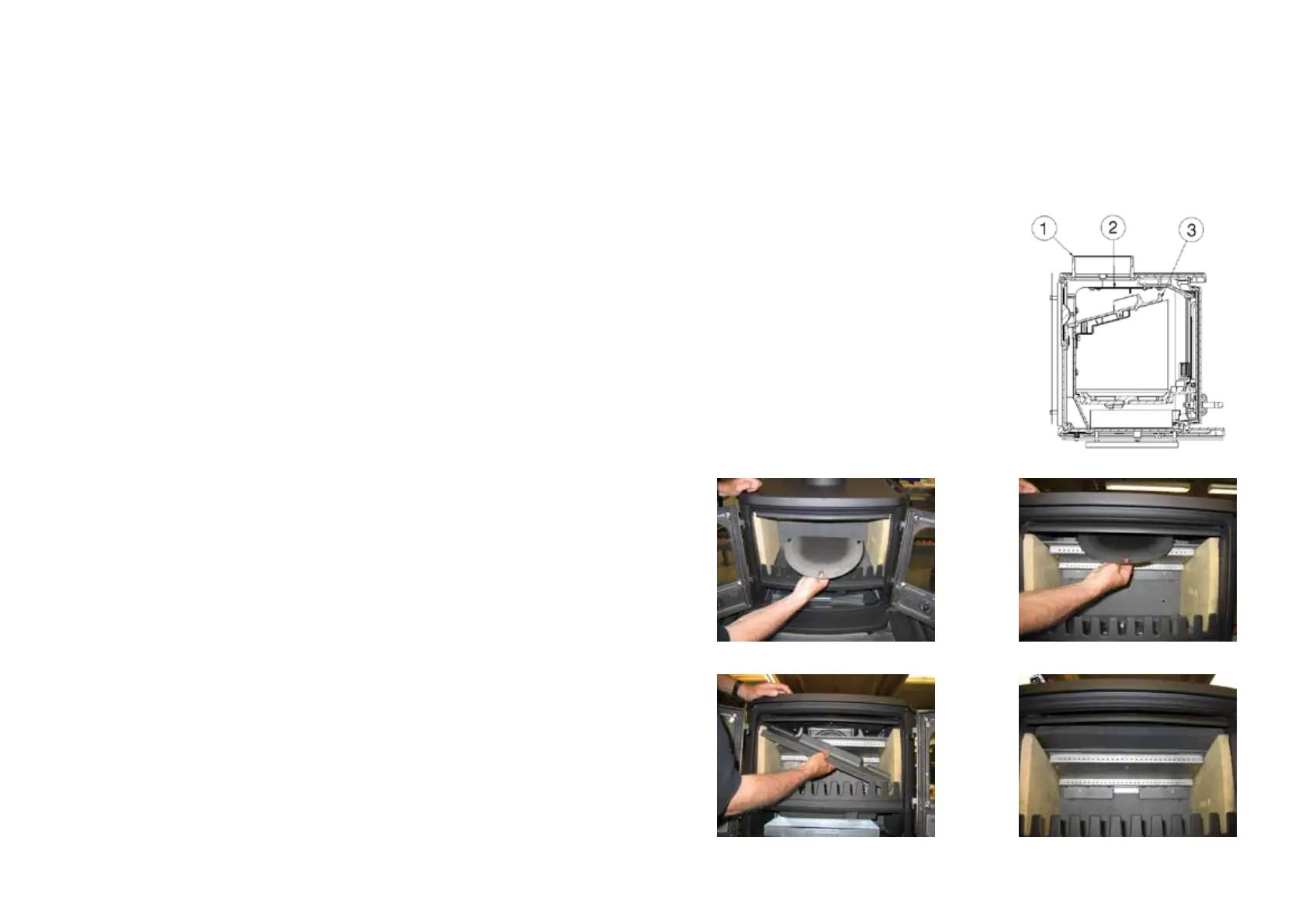
Remove the cast access bae (3). Lift the steel
smoke shield over the main bae assembly; lo-
cate the keyhole slots onto the 3 xing points
in the top of the rebox. Finally push the smoke
shield backwards until the keyhole slots are fully
engaged as shown on g. 1.2. Replace the access
bae (3) (g. 3-4).
If the stove is tted with a rear ue exit the ac-
cess bae (2) is not to be used. Ensure that the
bae plate (3), the re bricks, and the riddling
grate are positioned correctly.
Fig. 1
Fig. 3
Fig. 2
Fig. 4
 Loading...