02/12/16 CM1K90F_IT-EN-DE
ENGLISH
ENGLISH
Battery Flat
If the controller loses power during starting sequence due to bad battery condition, it will not try to start
again and will activate this protection.
Voltage Autodetect
If generator voltage measured doesn’t correspond with predened values for particular connection type
when Autodetect value for B04 Connection Type is used.
Generator Short Circuit
If the generator generator current exceed preset current limit.
Fuel Level SD
This shutdown occurs when analog input Fuel Level is below shutdown level or binary input Fuel Level SD
is closed longer than 10s.
REV.0-12/16
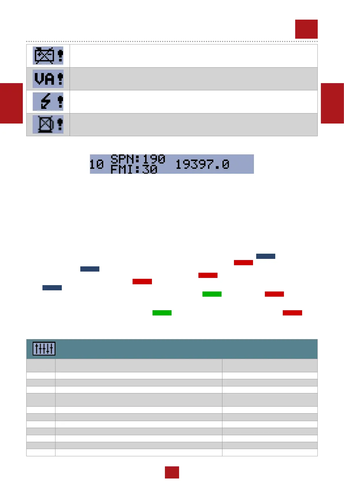
4.4 ECU Messages
ECU Message
Diagnostic messages are read and displayed in the history behind the ECU Warning symbol. For Standard J1939 SPN
(Suspect Parameter Number) and FMI (Failure Mode Identier) are shown.
Detail SPN/FMI code specication see in:
• SAE Truck and Bus Control and Communications Network Standards Manual, SAE HS-1939 Publication
• Or refer to corresponding engine manufacturer’s ECU error codes list.
Complete list of text diagnostic messages for each ECU can be found in ComAp Electronic Engines Support manual.
5 SETUP
5.1 Accessing the setup mode
Ensure the engine is stopped and the controller is in Manual mode (green LED above button
AUTO
is turned off).
If you have not congured the custom initialization (init) screen then press and hold
STOP
button, then briey press ▲
button and then
AUTO
.
If you have already created your own init screen then press and hold
STOP
button and then briey press ▲, the custom
init screen will appear, keep holding the
STOP
button. Then press ▼ to switch LCD to default init screen, and then press
AUTO
.
To move up and down in the setup menu use ▲ and ▼ buttons. Press
START
button to select or
STOP
button for exit.
5.2 Setpoints
Use ▲ and ▼ buttons to move or change value.
START
button to select setpoint or conrm changes and
STOP
button
to go back.
Basic setting
Setpoint
code
Setpoint name
B01 Nominal Voltage Ph-N 80 – 480 V
B02 Nominal Voltage Ph-Ph 80 – 600 V
B03 Nominal Frequency 50 Hz (1), 60 Hz (2)
B04 Connection Type Mono Phase (1), SplitPhase (2),
3Ph3Wire (3), 3Ph4Wire (4)
B05 Units Format Metric unit format (1), US unit format (2)
B06 AMF Function
Disable (1), Enable (2)
B07 Zero Power Mode Delay 0-360 min
B08 Light Tower Mode Disable (1), Enable (2)
B09 Nominal Current 1 - 1000 A
B10 CT Ratio 1 - 5000 A
B11 Nominal RPM 100-4000
ECU MESSAGE
 Loading...