Do you have a question about the Mosa COMAP IntelliLite AMF25 and is the answer not in the manual?
Generator cannot be started; STARTER, GCB/MCB exits are inactive.
Allows manual start/stop and GCB/MCB control when voltage is within limits.
Controller responds to mains presence; engine start/stop determined by POWER.
Generator starts automatically and runs without charge; takes charge on power failure or MCB press.
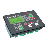
Describes the graphic LCD display, status LEDs, and function of control buttons.
Lists generator/engine measures and critical protections like overload, overvoltage, and overspeed.
Details AMF functions, general features, and communication interface options.
Details the function of control buttons: Start, Stop, Fault Reset, Horn Reset, Mode, GCB, MCB.
Describes the function of status LEDs: GEN-SET FAILURE, GEN-SET VOLTAGE OK, GCB ON, MCB ON, MAINS VOLTAGE OK, MAINS FAILURE.
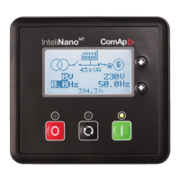
Details the graphic display and control buttons for navigation: Page, Up, Down, Enter.
Displays measured values (voltages, current, oil pressure) and computed values (power, statistics, alarms).
Contains all setpoints organized into groups, including a section for password entry.
Shows the history log in reverse chronological order (last record first).
Describes alarm states: Inactive unconfirmed alarm, Active unconfirmed alarm, Active confirmed alarm.
Details the procedure for navigating through ECU (Engine Control Unit) alarms on the controller display.
Explains how to modify setpoints, noting password protection for certain parameters.
Guides the user through the process of entering the password to access protected settings or features.
Describes how to adjust the contrast of the controller's display for better readability.
Shows how to access and view controller information, including serial number and software version.
Step-by-step guide to reset hour/maintenance alerts after performing service or maintenance.
| Manufacturer | Mosa |
|---|---|
| Model | COMAP IntelliLite AMF25 |
| Category | Control Unit |
| AMF | Yes |
| Frequency | 50/60 Hz |
| Inputs | Digital and Analog |
| Communication | Modbus |
| Operating Temperature | -20 to +70 °C |
| Certifications | CE, UL |
| Display | LCD |
| Application | AMF |
| Outputs | Relay Outputs |
| Communication Ports | RS485 |
| Humidity | 95% non-condensing |
| Power supply | 100-240V AC |