02/12/16 CH7K20C1_IT-EN-DE
ENGLISH
ENGLISH
POSITION BUTTON DESCRIPTION
15 Graphic B/W display, 128x64 pixels
16
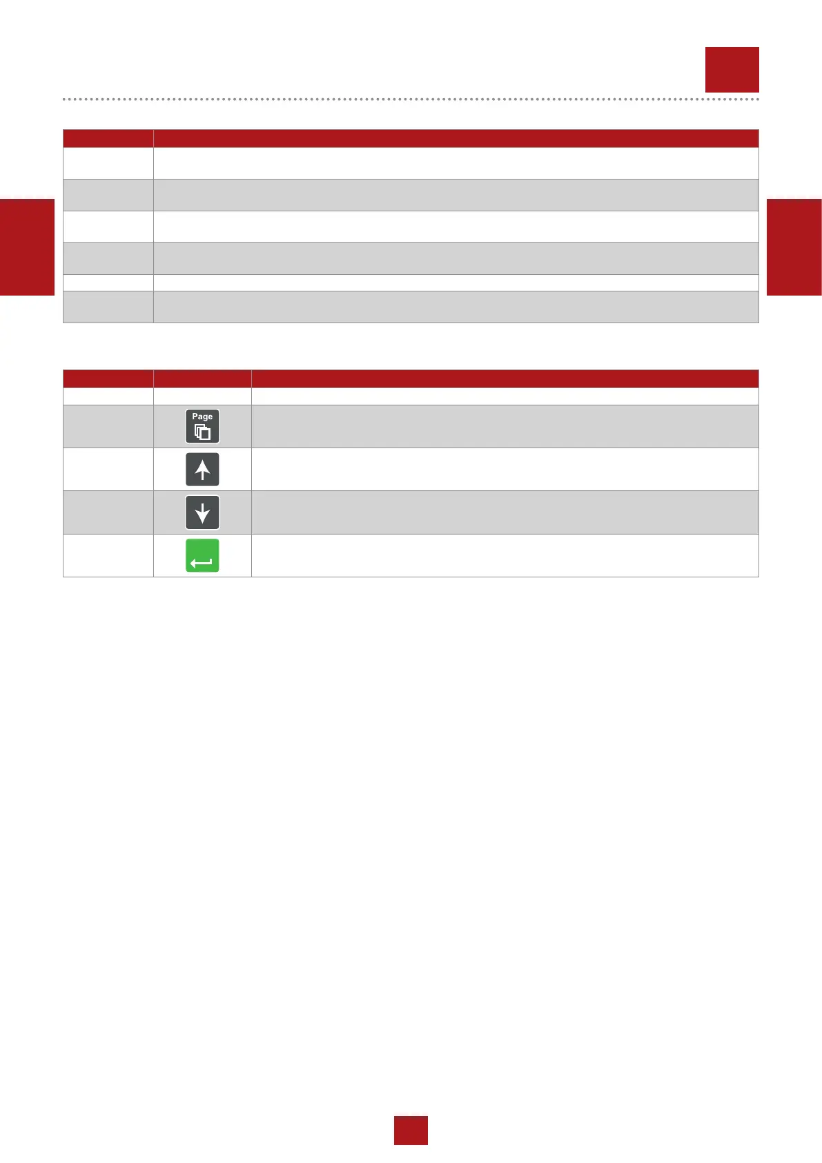
PAGE BUTTON: Use this button to switch over display pages. See Display Screens and
Pages Structure chapter below this table for more details.
17
UP BUTTON: Use this button to move up or increase a value.
18
DOWN BUTTON: Use this button to move down or decrease a value.
19
Enter
ENTER BUTTON: Use this button to nish editing a setpoint or moving right in the history
page.
POSITION DESCRIPTION
9
GEN-SET FAILURE: Red LED starts ashing when gen-set failure occurs. After FAULT RESET button is pres-
sed, goes to steady light (if an alarm is still active) or is off (if no alarm is active).
10
GEN-SET VOLTAGE OK: Green LED is on if the generator voltage is present and within limits.
Note: The limits for the generator voltage and frequency are given by setpoints in the Gener Protect group.
11
GCB ON: Green LED is on, if GCB is closed. It is driven by GCB CLOSE/OPEN output (AMF 8/9) or by GCB
feedback signal (AMF 20/25).
12
MCB ON: Green LED is on, if MCB is closed. It is driven by MCB CLOSE/OPEN output (AMF 8/9) or by MCB
feedback signal (AMF 20/25).
13 MAINS VOLTAGE OK: Green LED is on, if mains is present and within limits.
14
MAINS FAILURE: Red LED starts blinking when the mains failure is detected and after the gen-set has started
and connected to the load it lights permanently until the mains failure disappears.
GEN-SET OPERATION INDICATORS
DISPLAY AND CONTROL BUTTONS
REV.0-12/16
CONTROLLER AMF25
 Loading...