PRO-67-B V.2.S
the smaller splices, align the numbers 1, 1, 1, which will position the holes correctly and secure with hardware
(parts 61, 62, 63). Repeat this using the 3,3,3 for the last boom joint.
< > Place caplug (part 64) on each end of boom.
< > Check that all bolts are tight, and have lock washers in place.
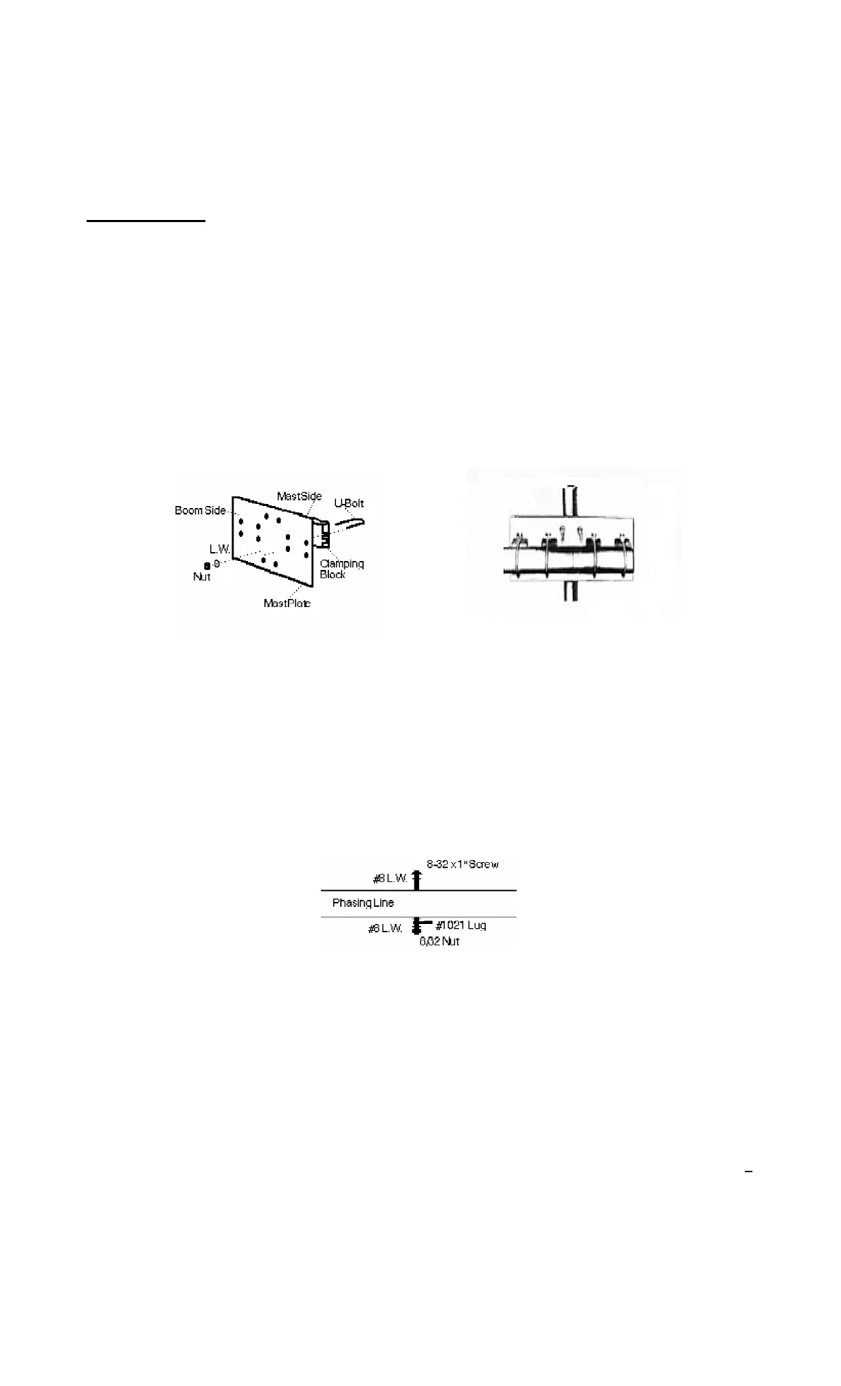
ASSEMBLY AND PLACEMENT OF MAST PLATE
< > Place the mast plate on the boom (Part 31) between the RED COLOR CODE on the boom for the BDE, but
between the BROWN COLOR CODE of the Front Driven Element, (FDE).
< > Place 4 #47 clamping blocks (part 30) between the boom and the mast plate and secure with the four 2"
U-bolts (part 24).
< > Secure the U-bolts with lock washers and nuts (parts 26, 27).
DO NOT TIGHTEN AT THIS TIME. ONCE ALL ELEMENTS ARE IN PLACE, THE MAST PLATE WILL NEED
TO BE MOVED BETWEEN THE RADIATORS TO GET THE BEST BALANCE POINT.
ASSEMBLY OF PHASING LINES
< > These two lines (part 27) are used between the Front Driven Element and the Back Driven Element..
These lines connect the two driven elements together, putting them in phase with each other.
< > Place the 8/32 x 1" screw, lock washers, and nut to each side of the phasing lines. (Parts 29, B, C). Set
aside until needed.
Completed Plate
Boom
Mast
6