Do you have a question about the Motoalliance Denali Series and is the answer not in the manual?
Essential safety guidelines for operating the plow system, covering passenger limits, speed, and protective gear.
Attach the Wear Bar to the blade using carriage bolts, nuts, and washers.
Secure skid feet brackets to the blade using hex head bolts, washers, and nuts.
Mount skid feet with washers and bushings, adjusting height and securing with lynch pins.
Final check of all bolts for security after blade setup.
Attach Swivel Plate Assembly to Lift Arm Assembly with specific bolts, washers, and nuts.
Connect Pivot Lever Support Bracket to the Lift Arm Assembly using bolts and washers.
Connect Pivot Lever Risers to Lift Arm Assembly, pending final tightening.
Connect Pivot Lock Lever to Pivot Lever Risers with specific hardware and spring.
Mount the Winch Attachment Bracket using bolts and washers.
Secure Blade Stop Blocks with bolts, washers, and nuts to prevent excessive blade pullback.
Connect the plow blade to the Swivel Plate using bolts, washers, and nuts.
Connect extension springs between the blade and eye bolts, adjusting tension for blade support.
Use quick release pins and washers to attach pushtube to mount tabs securely.
Recommendations for securing the plow during long-distance transport to minimize bouncing.
Explanation of design features like over-centered blade and attack angle for snow transition.
Details on the three-year warranty against manufacturing defects, excluding user error and consumables.
Advice on preventing rust by applying protective paint to exposed metal surfaces.
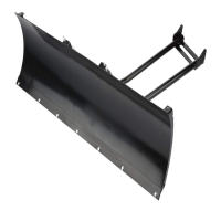
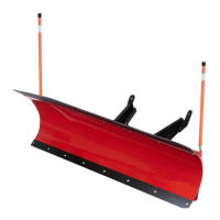
The Denali 66" & 72" Plow Blade & Pushtube Assembly is a robust snow plow system designed for efficient snow removal. Engineered in the USA, this system focuses on durability and ease of use, incorporating features like added horizontal supports, a specific attack angle, a kick pedal locking mechanism, and weld nuts under the pushtube for straightforward installation. It is intended to provide reliable performance for many years.
The primary function of the Denali Plow Blade & Pushtube Assembly is to clear snow from various surfaces. The system is designed to attach to a UTV, transforming it into an effective snow removal machine. The plow blade, available in 66" and 72" sizes, is engineered with an over-centered design and a 65° attack angle. This specific design ensures that snow is efficiently transitioned up the plow blade and rolled forward, rather than building up in front of the blade or creating large side walls that fall back onto the plowed path. This process also helps remove air from the snow, contributing to more effective plowing. The 65° attack angle is also crucial for maximizing the life of the wear bar and reducing wear on the plowing surface itself.
The pushtube assembly connects the plow blade to the vehicle, providing the necessary structural support and articulation for plowing. It includes a swivel plate assembly that allows the blade to pivot, enabling angle adjustments to direct snow as needed. A pivot lock lever mechanism is integrated to secure the blade at the desired angle, which can be easily adjusted by the user. The system also incorporates extension springs that add tension to the blade, helping to hold it upright and preventing it from tipping forward during plowing. Blade stop blocks are included to prevent the blade springs from pulling the blade back too far, ensuring proper operation. A winch attachment bracket is also part of the assembly, facilitating the connection of a winch for raising and lowering the plow blade.
The Denali Plow Blade & Pushtube Assembly offers several features that enhance its usability and performance:
Maintaining the Denali Plow Blade & Pushtube Assembly is straightforward, focusing on ensuring longevity and optimal performance:
| Starting System | Electric Start |
|---|---|
| Auger Material | Steel |
| Clearing Height | 21 in. |
| Engine | Honda |
| Auger Type | Two-Stage |
| Chute Rotation | 200 Degrees |
| Displacement | 270cc / 390cc |