EasyManua.ls Logo

Motorline professional MC112PR - User Manual

Motorline professional MC112PR
20 pages
Print Icon
To Next Page IconTo Next Page
Loading...
V3.0
REV. 08/2022
MC112PR | MC113PR | MC114PR
EN
USER’S AND INSTALLER’S MANUAL
Question and Answer IconNeed help?

Do you have a question about the Motorline professional MC112PR and is the answer not in the manual?

Summary

01. SAFETY INSTRUCTIONS

General Safety Warnings

Crucial safety and usage information for careful reading before product installation.

Warnings for Technicians

Essential precautions and checks for technicians during installation and setup procedures.

Warnings for Users

Advises users on safe product handling, maintenance, and emergency procedures.

Supplier Responsibility

Details liabilities and warranty conditions for improper installation, use, or modifications.

02. PRODUCT

Description of Product

Details control board capabilities: motor compatibility, soft start/stop, and speed regulation.

Components Map

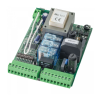
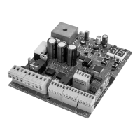
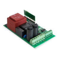
Illustrates and lists the components that comprise the control board.

03. COMPONENTS

MR13 Receiver

Explains the function and programming of the MR13 Rolling Code remote controls receiver.

MF2020 Photocell

Describes the MF2020 column photocell, its function, and operating modes for safety.

04. INVERTERS AND CONNECTORS

Frequency Inverters

Introduces frequency inverters (MC112PR, MC113PR, MC114PR) and their power ratings.

Frequency Inverters Connections

Details the inputs and outputs of the frequency inverter panel for wiring.

Connections Connectors

Illustrates and explains the inputs and outputs of the connection connectors.

05. CONNECTIONS SCHEME

Frequency Inverter Connections

Provides a wiring diagram for connecting the frequency inverter.

MR13 Receiver Connections

Shows the wiring diagram for connecting the MR13 receiver to the system.

Other Connections

Illustrates connections for magnetic loop detector, resistor, and push button.

Closing Pre-Flashing Light

Details the wiring for the optional closing pre-flashing light feature.

UPS Unit Connection

Explains how to connect the UPS unit for backup power supply.

Relay for Two-Door Interlock

Shows the wiring scheme for implementing a two-door interlock system.

External Components Connections

Illustrates wiring for external components like photocells, sensors, and LEDs.

06. DESCRIPTIONS

Digital Numeric Keyboard

Describes the functions of the digital numeric keyboard buttons and display indicators.

Menu Navigation

Explains how to navigate through the system's menus using control panel buttons.

Lock;Unlock Keyboard

Details the procedure for setting up and using a password to lock/unlock the keyboard.

Programming Menu Access (Menu 04)

Guides users on accessing the main programming menu (Menu 04).

Programming Menu - 04

Lists and explains the parameters available within Programming Menu 04.

07. PROGRAMMING

Slowdown Adjustment

Provides a step-by-step guide to adjust the door's slowdown speed during operation.

LED Display Messages

Lists and explains various messages displayed on the LED indicator and their meanings.

08. TROUBLESHOOTING

Instructions for Consumers and Specialized Technicians

Offers guidance on identifying and correcting common faults and errors in the system.

Overview

The Motorline MC112PR, MC113PR, and MC114PR are control boards designed for automating industrial doors, offering a range of features for enhanced reliability, durability, and user convenience. These devices are certified in accordance with European Community (EC) safety standards and comply with Directive 2011/65/EU (RoHS) regarding the restriction of hazardous substances in electrical and electronic equipment. Users are advised to consult the manual for proper recycling procedures and to be aware of potential electric shock hazards.

Function Description:

The core function of these control boards is to manage the operation of industrial door motors, ranging from 750W to 2200W. They incorporate a frequency inverter, which enables a soft start and stop mechanism, significantly contributing to the product's reliability and extending its lifespan. The control board allows for precise regulation of both opening and closing speeds, as well as the adjustment of slowdown speeds during both phases of operation.

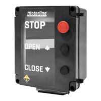
A key feature is the intuitive display for easy navigation and adjustment of various parameters and menus. The system also includes a "Human Presence" function, allowing the door to open with an impulse until it reaches the limit switch, and requiring continuous pressing of the close button to close the door. It tracks the number of cycles performed by the door (one complete opening and closing constitutes one cycle), providing valuable usage data.

The control boards are compatible with Motorline's Rolling Code remote controls via the MR13 receiver and support the connection of MF2020 Photocells for enhanced safety.

Important Technical Specifications:

  • Power:
    • MC112PR: 750W max
    • MC113PR: 750W to 1500W
    • MC114PR: 1500W to 2200W
  • Power Supply: 230Vac 50/60Hz
  • Protection Class: IP64
  • Working Temperature: -25°C to 55°C
  • Relative Humidity: <90%
  • Accessory Output: 24Vdc 3W / 12Vdc 2W
  • Maximum Frequency Output: 90Hz
  • Dimensions:
    • MC112PR: 185mm (H) x 72mm (W) x 40mm (D)
    • MC113PR/MC114PR: 252mm (H) x 87mm (W) x 54mm (D)

Components Map:

The control board assembly includes:

  1. Frequency inverter
  2. Connections connectors
  3. MR13 Receiver
  4. Braking resistor
  5. Magnetic loop detector (Optional)
  6. Quick connection plug
  7. STOP button
  8. Opening button
  9. Closing button
  10. MF2020 column photocell

MR13 Receiver:

  • Learn Button: Used to program Rolling Code Motorline remote controls. Press once, then press the desired button on the remote. To reset memory, press for 10 seconds.
  • LEDs:
    • LED1: Power indicator (ON for 230Vac).
    • LED2: "SEC" contact status (ON for closed).
    • LED3: "STR" contact status (ON for closed).
    • LED4: Programming LED.
  • Connectors: L/N (230Vac power input), SIG (frequency inverter pulses), R/G/B (RGB LED connection), +/- (power supply for external accessories, max 150mA), SEC (NC safety signal output, not used), STR (NO open signal output), ANT (Antenna hot pole input), ✔ (Antenna mass input).

MF2020 Photocells:

  • Designed for industrial doors up to 10 meters wide, offering protection up to 2.5 meters high.
  • Operating Modes: Static, Sequential, and Sequential for transparent tarpaulins. Default is Sequential (max speed 1.4 m/s).
  • Status LED (Photocell RX): Blinks once every 2 seconds (Sequential), Always ON (Static), Blinks twice every 2 seconds (Sequential for transparent tarpaulins).
  • Changing Mode: Turn off power, cover sensors 6 and 9 on the RX cover, reconnect power, then uncover sensors 6 and 9.

Usage Features:

  • Digital Numeric Keyboard: Provides status display (RUN, FWD, REV, STOP FLASHING, STOP OFF, PLC), LED display (frequency, voltage, current, units), UP/DOWN arrows for parameter adjustment, MODE for display modes, STOP/RESET for device restarts, and ENTER for programming.
  • Menu Navigation: Access and adjust parameters through a hierarchical menu structure.
  • Keyboard Lock/Unlock: Password-protected keyboard locking. Allows temporary unlocking for parameter changes. Factory reset option available by entering a specific code and holding ENTER.
  • Programming Menu (Menu 04): Offers extensive customization:
    • 04.00 OPEN SPEED: Adjusts door opening speed (0.00 to 70.00 Hz).
    • 04.01 CLOSE SPEED: Adjusts door closing speed (0.00 to 60.00 Hz).
    • 04.02 OPENING DECELERATION SPEED: Sets deceleration speed during opening (0.00 to 40.00 Hz).
    • 04.03 CLOSING DECELERATION SPEED: Sets deceleration speed during closing (0.00 to 40.00 Hz).
    • 04.50 LENGTH OPENING DECELERATION: Sets the length of deceleration during opening (0 to 1000).
    • 04.51 LENGHT CLOSING DECELERATION: Sets the length of deceleration during closing (0 to 1000).
    • 04.52 PAUSE TIME: Sets the time the door remains paused when open (0 to 99 seconds).
    • 04.53 HUMAN PRESENCE: Enables or disables human presence mode (0=Disabled, 1=ON).
    • 04.54 OPERATING LOGIC: Selects working modes (0=Step by step, 1=Condominium, 2=Inversion).
    • 04.55 ACCELERATION RAMP AT OPENING: Adjusts opening acceleration ramp time (0 to 30).
    • 04.56 ACCELERATION RAMP AT CLOSING: Adjusts closing acceleration ramp time (0 to 30).
    • 04.57 PEDESTRIAN OPENING TIME: Sets the duration of pedestrian opening (0 to 100).
    • 04.58 DECELERATION RAMP AT INVERSION: Sets deceleration time at inversion (0 to 20).
    • 04.59/04.60 MANEUVER COUNT: Displays total maneuvers performed by the automation.
    • 04.61 FLASHING LIGHT OUTPUT: Configures flashing light logic (0=active only when motor working, 1=active until closing limit switch, then ON for courtesy light time).
    • 04.62 RESET MANEUVER COUNT: Resets maneuver count (requires password).
    • 04.63 COURTESY LIGHT TIME: Adjusts the time the light remains on after reaching the limit switch (0 to 50 Min).
    • 04.64 PROGRAMMING MENU: Places control board in course programming (0 to 1).
    • 04.65 REVERSE SLOWDOWN ADJUSTMENT: Adjusts inversion slowdown (0 to 1000).
  • Slowdown Adjustment: A specific programming sequence is provided to adjust the slowdown at opening and closing, involving setting parameter 04.64 to 1 and using the OP button or remote control to mark the start and end of slowdown phases.

Maintenance Features:

  • Troubleshooting (LED Display Messages): The device provides various LED messages to indicate operational status and potential faults, aiding in diagnosis:
    • F60.0: Master frequency of AC inverter.
    • 450.0: Effective output frequency.
    • 85.0: Output current.
    • Frd: Door in opening.
    • rtu: Door in closing.
    • C 00: Input indications (common input or PLC1 parameter in PLCO, or 24V short circuit).
    • PLCI: Mandatory mode for operation.
    • EF: External fault.
    • End: Input accepted.
    • Err: Input invalid.
    • Sto: STOP enable crank sensor.
    • C111: Limit switch enabled, opening button pressed.
    • C222: Limit switch enabled, closing button pressed.
    • C333: Nothing activated.
    • C444: Opening limit switch enabled, descent button pressed.
    • C555: Closing limit switch enabled, descent button pressed.
    • C888: Photocells enabled.
    • C101: Ascent limit switch enabled.
    • C202: Descent limit switch enabled.
    • C999: Emergency stop, STOP, or crank sensor.
    • C800: No connection/limit switches and safety.
  • Troubleshooting (Fault Identification and Corrections):
    • OVERCURRENT: Check motor power, wiring for short circuits, loose contacts, overload conditions.
    • OVERVOLTAGE: Check input voltage, voltage variations, power for brake.
    • LOW VOLTAGE: Check input voltage, motor load, power connections.
    • OVERLOAD: Check if motor is overloaded, use appropriate AC motor inverter power.
    • OVERLOAD DURING ACCELERATION: Check motor output isolation, increase acceleration time.
    • OVERCURRENT DURING DECELERATION: Check motor output isolation.
    • DETECTION OF EFFORT AND EXCESS OF CONSUMPTION: Adjust parameter 06.04 (lower sensitivity), check for door obstructions.

General Safety and Usage Guidelines:

  • The manual emphasizes that installation and repair should only be performed by qualified technicians.
  • Regular inspections of installations for wear and tear are recommended.
  • Disconnect power during maintenance, cleaning, or part replacement.
  • Children should not play with the product or opening devices.
  • Technicians must ensure all necessary devices and materials are available before installation, verify the product's IP rating and operating temperature, and provide the user with the manual and emergency handling instructions.
  • Safety devices must protect against crushing, cutting, and other hazards.
  • The control unit must be installed in a safe, dry, dust-free location.
  • Electrical cables should be routed through protective tubes and enter the central unit from the bottom.
  • A permanent label for manual release should be attached near the mechanism.
  • The product should be connected to an electrical panel with ground connection if it requires 230Vac or 110Vac.
  • The warranty is voided if product failure results from improper installation, use, or maintenance, non-compliance with safety norms, or unauthorized modifications.

Motorline professional MC112PR Specifications

General IconGeneral
BrandMotorline professional
ModelMC112PR
CategoryControl Unit
LanguageEnglish

Related product manuals