Do you have a question about the Motorline professional MC60 and is the answer not in the manual?
Important safety and usage information. Read all instructions carefully before installation/usage procedures.
Installation procedures, site suitability, and emergency handling guidelines for technicians.
Manual consultation, product use, and emergency handling guidance for end-users.
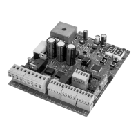
Technical specifications of the MC60 control board including power supply, outputs, and working temperature.
Detailed description of all input and output connectors on the control board.
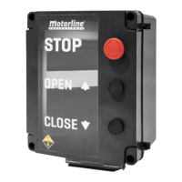
Explanation of the control buttons and status indicator LEDs on the control board.
Diagram illustrating the electrical connections for sliding gates.
Diagram illustrating the electrical connections for sectional doors.
Diagram illustrating the electrical connections for barriers.
Diagram illustrating the electrical connections for automatic bollards.
Diagram illustrating the electrical connections for master-slave configuration.
Step-by-step guide for the initial installation of the control board and accessories.
Procedure for programming and erasing remote controls for gate operation.
Overview and access instructions for programming menus starting with 'P'.
Overview and access instructions for programming menus starting with 'E'.
Table showing exclusive factory values for different system types.
Procedure for automatic or manual programming of the gate's opening and closing course.
Adjusts the slowdown time at the opening and closing of the gate.
Sets the opening/closing force and sensitivity to obstacles.
Schedules the gate opening time for pedestrian passage.
Sets the total opening pause time for automatic closing.
Programs the security behavior for the first photocell input.
Programs the security behavior for the second photocell input.
Sets the operating logic for automatic, step-by-step, or condominium modes.
Sets the operation mode of the flashing light (LAMP).
Enables/disables remote programming without direct access to the control board.
Configures human presence, pushbutton mode, and emergency stop inputs.
Enables or disables the soft start function for gradual motor speed increase.
Adjusts the courtesy light activation time when the gate is closed, opened, or stopped.
Activates Follow Me option, triggering closing after safety device detection.
Adjusts the working time for opening and closing courses at normal speed.
Activates electronic brake and configures the LK output behavior (lock).
Adjusts the slowdown speed for the gate opening and closing.
Displays the number of maneuvers performed by the gate.
Resets the control board to factory default settings.
Configures the output mode for RGB lights (continuous or flashing).
Table showing the meaning of different codes displayed on the control board.
Guide to diagnose and resolve common anomalies with procedures for users and technicians.
| Brand | Motorline professional |
|---|---|
| Model | MC60 |
| Category | Control Unit |
| Language | English |