Do you have a question about the Motorline professional SLIDE1024 and is the answer not in the manual?
Provides crucial safety and usage information. Read all instructions before installation and keep the manual for reference.
Instructions and precautions specifically for qualified and specialized technicians performing installation and repairs.
Supplier disclaims liability for product failure due to improper installation, use, maintenance, or unauthorized modifications.
Explains the meaning of various symbols used in the manual for safety, information, and programming.
Details the technical specifications of the automated system for sliding gates, including power, speed, and environmental ratings.
Lists all items included in the automation package that should be checked before beginning the installation process.
Diagram illustrating the placement of various components for the gate automation system during installation.
Step-by-step guide on how to change the orientation of the motor unit, especially if battery access is obstructed.
Instructions on how to manually unlock the gate's automatism using a key and unlocker for manual operation.
Procedure for creating or using an existing shoe for the engine mounting plate, including concrete preparation.
Detailed steps for securely installing the motor unit onto the fixing plate and connecting electrical cables.
Procedure for installing the metal rack onto the gate, ensuring proper alignment and engagement with the motor pinion.
Instructions for installing the nylon rack, a different type of rack, onto the gate and securing it to the pinion.
Guide on how to install and adjust mechanical or magnetic limit switches to control the gate's opening and closing limits.
Procedure for testing the motor's functionality by direct connection to a 24V battery, aiding in fault detection.
Regular maintenance tasks including checking the rack, support plate, and lubricating moving parts for optimal performance.
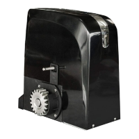
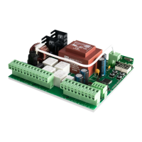
The Motorline SLIDE1024 is an automated system designed for residential and industrial sliding gates. It features an electro-mechanical gearmotor powered by a 24V control unit, capable of handling gates with a maximum weight of 1000kg. The system incorporates a programmable electronic control board, allowing users to customize function logics, work time, pause time, anti-crushing sensitivity, and partial-opening width. A key safety feature is its reversing system, which automatically locks the gate when the motor is not in operation. In case of malfunction or emergency, a release system enables manual gate movement.
The SLIDE1024's primary function is to automate the opening and closing of sliding gates. The control unit manages the motor's operation, ensuring smooth and controlled movement. The programmable nature of the system allows for tailored operation, adapting to various user needs and gate types. For instance, the anti-crushing sensitivity can be adjusted to prevent injury or damage if an obstacle is detected. The partial-opening width feature is useful for pedestrian access, allowing the gate to open only partially. The system is designed for intensive use, making it suitable for both residential and industrial applications where frequent gate operation is required.
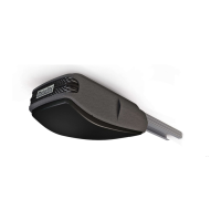
The SLIDE1024 offers several features that enhance its usability and safety. The manual unlock mechanism is a crucial safety feature, allowing the gate to be opened or closed manually during power outages or system malfunctions. This involves inserting a key and turning it 90 degrees, then pulling out the unlocker. Once the issue is resolved, the unlocker can be closed and the key turned to re-engage the automatism.
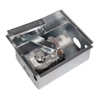
The system's orientation can be changed during installation if an obstacle prevents access to the batteries. This involves unscrewing the fastening plate, rotating the engine body, tightening the screws, rotating the entire motor and plate assembly to direct the pinion to the rack, tightening the fixing screws to the ground, and finally inserting the cover. This flexibility ensures that the system can be installed in various configurations while maintaining accessibility for maintenance.
Installation of the metal rack involves placing spacers in all rack holes, positioning a rack piece on the pinion, leveling it, and welding the spacer. The gate is then moved to allow the rack to rest against the pinion, and additional rack pieces are applied, ensuring proper synchronization of the teeth. The process is repeated for the entire length of the rack, with manual testing of gate movement to identify and adjust any friction. For nylon racks, the process is similar, involving securing the rack over the pinion to the gate and fitting additional pieces.
Limit switches are essential for defining the gate's opening and closing positions. The SLIDE1024 supports both mechanical and magnetic limit switches. For mechanical limit switches, plates are positioned on the rack to stop the engine before the gate reaches its physical stops. These plates are secured with screws, and the process is repeated for both opening and closing positions. The mechanical limit switch activates when the plate contacts a spring. For magnetic limit switches, magnets are positioned on the rack to trigger the engine stop. The magnetic field position can be adjusted, and the magnetic limit switch activates when the magnet aligns with the reader on the engine. It is crucial to tune the limit switches correctly to prevent the gate from hitting its physical stops.
Before connecting the motor to electric current, it is recommended to test the drive with the door unlocked manually to avoid problems due to poor configuration. This ensures that the gate stops at the intended positions.
Regular maintenance is crucial for the longevity and optimal performance of the SLIDE1024. The manual outlines several key maintenance tasks that should be performed within six months to ensure correct operation.
One important aspect is checking the rack. It is essential to ensure that the distance between the rack and the motor remains unchanged and that the motor pinion correctly engages with the rack teeth. Over time, some distortion may occur, which can affect the system's performance. Additionally, the rack must remain securely attached to the gate.
Lubrication is another critical maintenance task. All gate drive systems and shafts should be lubricated with fine oil. This helps reduce friction and wear, ensuring smooth operation of the gate.
Checking the support plate is also necessary. The brackets must remain securely attached to the pillars and the gate for the equipment to function properly. Loose brackets can lead to instability and potential damage to the system.
For troubleshooting, the manual suggests performing tests by directly connecting the engine to an external 24V DC battery. This allows technicians to identify faulty components. When connecting the wires to the battery, the motor should operate in one direction. To test the reverse movement, the position of the wires connected to the battery should be changed. These tests can be performed without removing the automation from its installed location, allowing technicians to observe if the system works correctly when directly powered. All electrical tests must be carried out by specialized technicians due to the inherent dangers of electrical systems.
The manual emphasizes the importance of proper installation and maintenance to ensure the product's safety and functionality. It warns against improper installation, use, or maintenance, as these can lead to product failure, deformation, and void the warranty. Unauthorized modifications are also discouraged for the same reasons.
| Model | SLIDE1024 |
|---|---|
| Brand | Motorline |
| Power Supply | 230V AC |
| Max Door Weight | 1000kg |
| Control Type | Remote control |
| Operating Temperature | -20°C to +50°C |
| Protection Rating | IP44 |
| Limit Switch Type | Mechanical |
| Manual Release | Yes |
| Safety Features | Obstacle detection |
| Installation Type | Surface mount |